
UNITED STATES HARBOR DEFENCES - USCG CABLE SHIP PEQUOT
 |
Design & Construction of the
General Samuel M. Mills 1908-09 Ship Plans – National Archives and Records Administration Construction Photos – Independence Seaport Museum Archives, New York Shipbuilding records www.phillyseaport.org/library |
 |
This page provides more detail about the U.S. Coast Guard Cable ship
Pequot during World War II.
It describes the
design and construction of the US Army mineplanter General Samuel M. Mills
later renamed the USCG Pequot. It was as the Pequot the ship carried
out vital harbor defense cable-laying program along the eastern seaboard
of the USA. Our main page for the USCG
Pequot provides extra
details about the ship, its crew, its purpose as well as links to our other
Pequot pages. Research and design by by Chip Calamaio and Richard Walding.
 |
|
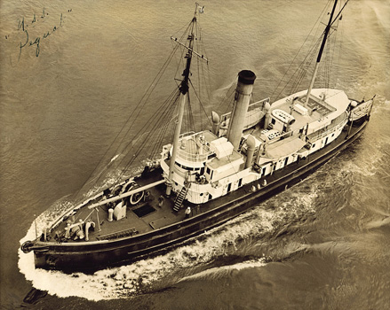
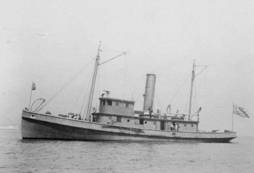
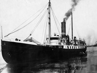
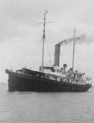
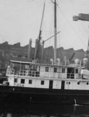
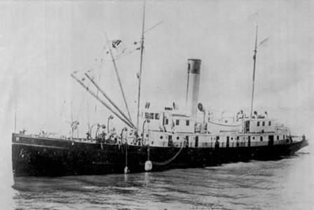
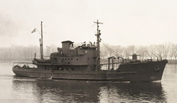
The US Coast Guard Pequot (previously The General Samuel M. Mills). During WWII this cable ship laid top secret Indicator Loop cables to protect harbors from German U-boats. Her mission ranged from the ports of Virginia up to Argentia, Newfoundland. (Calamaio family). |
THE BEGINNINGS
When the USCG
Pequot was built as the US Army mine
planter, the
General Samuel M Mills, she was constructed at the New York
Shipbuilding Company in Camden, New Jersey along with two identical sister
ships, the
General Royal T. Frank and the
General John. M. Schofield under a
contract with the Submarine Mine Service of the US Coast Artillery Corps which
was under the War Department, US Army, Office of the Quartermaster General. The
ship was named after Brigadier General Samuel Meyers Mills, Jr. who was the
U.S. Army’s Chief of Artillery 1905-1906.
 |
 |
|
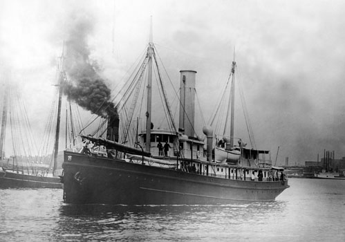
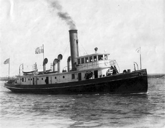
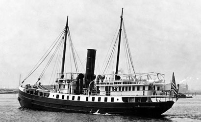
The
General
Samuel M. Mills during sea trials 1909.
|
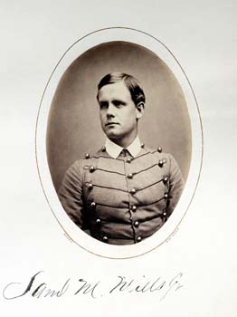
Cadet Samuel M. Mills in 1865 (Special Collections, US Military Academy Library, West Point) |
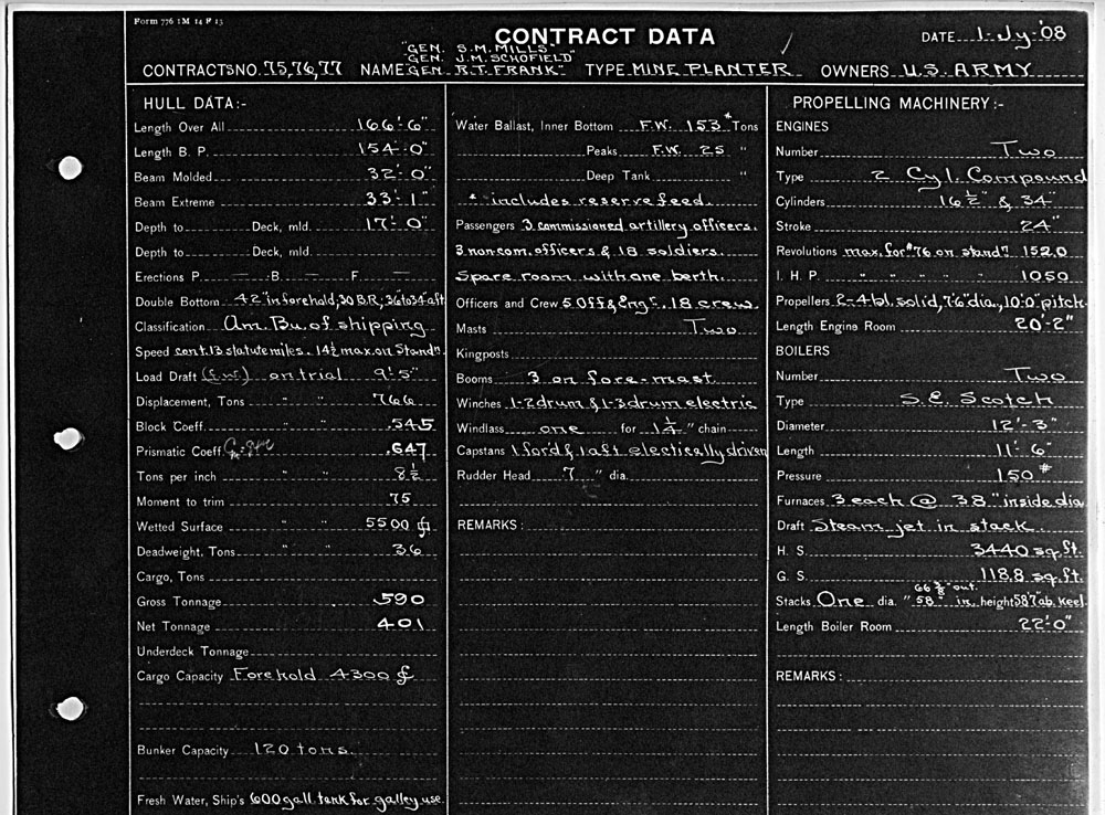
On July 1st 1908 contracts 75, 76 & 77 were awarded for three “Twin Screw Steel Steamers” which were built simultaneously under the huge covered shipbuilding ways K and L at Camden, off of the same plans, and to identical specifications. In fact the Mills and the Schofield both had their keels laid on the same day, October 12, 1908. Based upon what we’ve learned about the price tag for the Mills, the Army’s contract with New York Shipbuilding Company for these three ships in 1908 was approximately $900,000.
Located on a 160 acre site along the Delaware river across from Philadelphia, Pennsylvania the New York Shipbuilding company operated from 1899 to 1967. During WWII it was the largest and most productive shipyard in the world. Through the development of a revolutionary “template” system of building and prefabricating hull components for multiple ships to the same specifications at the same time, this technique pioneered by the company served American well during both world wars when ships of all types just couldn’t be built fast enough.
 |
|
New York Shipbuilding company (A Place Called Yorkship / yorkship.us) |
The contract for the Mills, Frank, and Schofield was among the first order for multiple ships that used an enormous mold loft where hull plates were fabricated from templates in the cavernous covered shipways K and L. These covered sheds were equipped with enormous cranes which could lift 100 tons. These immense buildings were also used during this period to build many of the Navy’s huge dreadnought battleships which saw action during World War I.
 |
 |
| (Independence Seaport Museum Archives). | (Click to Enlarge). (Independence Seaport Museum Archives). |
The era of naval architecture during which these ships were built can clearly be seen when looking at many small Coast Guard vessels and tug boats of the time. The design and lines of the General Samuel M Mills and her sister ships reflect the design influences of many these tall stack coal burning ships from the turn of the century.
 |
 |
| USCG Mackinac 1903. (Coast Guard Tug Association). | USS Saco in Port 1920s. (National Association of Fleet Tug Sailors). |
 |
|
Elevation Plan View – The General Samuel M. Mills. Click image to enlarge. |
 |
 |
|
USS
Seminole
also Built in Camden, NJ. (National Association of Fleet Tug Sailors). |
USS
Vigilant July 1898. (National Association of Fleet Tug Sailors). |
 |
 |
| The New
York Shipbuilding Company built eight 190 foot Manzanita class
lighthouse tenders in 1907 for the U.S. Lighthouse Service. These
ships were being fitted out and completed right before
construction started on the Mills, Frank and
Schoenfield. Even though these lighthouse tenders where
slightly longer, had a larger upper rear cabin, and covered
gangways along both sides, the similarity of design to the Army
mine planters of 1908-09 is striking. In fact, in the Annual
Reports of the War Department for Fiscal Year Ended June 30, 1906
it was noted, by Arthur Murray, Lieutenant Colonel, Artillery
Corps, Commandant that, “...these planters are seagoing lighters
modeled after one of the latest types of Light-House Service
tenders, arranged, equipped and manned especially for mine work." (Independence Seaport Museum Archives - both images). |
|
PLANS FOR THE GENERAL SAMUEL M. MILLS
We have been able to locate the original New
York Ship Building Company August and September 1908 design drawings for the
General Samuel M. Mills and her two sister ships. Our illustrations come
from electronic scans of four huge brownprint drawings which measure 5-7
feet in length. Most of these plans were signed by registered Naval
Architect, "J. Donald."
All slices & CUs of Pequot Aerial photo next to plan details
(unless otherwise noted below) - - Calamaio family.
 |
|
ELEVATION VIEW |
 |
|
PLAN VIEW |
 |
|
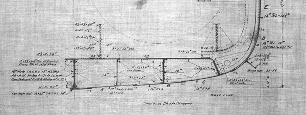
Here, in an elevation
view, we see half of the profile lines of the ship’s bow and half
of the profile of the stern. |
 |
|
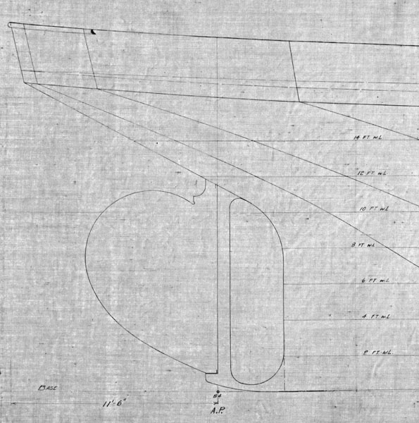
This detail of the stern and rudder uses two foot increments off the ship’s keel as a dimensional reference notated in feet of waterline “WL” above the keel. |
 |
|
|
Here in ascending order, we see water line reference dimensions off the keel on the inverted plan view of the hull. |
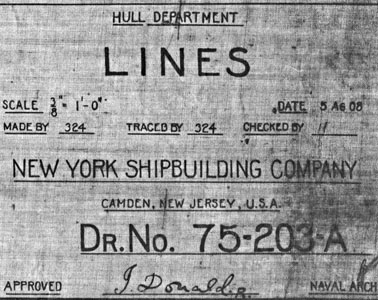
The title block of the hull drawing labels this drawing as “LINES” and is signed off on by Naval Architect “J Donald”. |
The General Samuel M. Mills was launched from
Shipway K on Feb 13th 1909 and after outfitting was delivered to the Army on
March 19, 1909. We’ve learned that after commissioning the Mills
was stationed out of Fort Monroe, Virginia in 1910. During peacetime between World War I and World War II, the
Army maintained a fleet of eight mine planters. Four served along the East
Coast of the United States, two were stationed for duty along the West
Coast, and two mine planters took care of business in Hawaii, the
Philippines, and along the Panama Canal Zone.
 |
 |
 |
|
(US Army
Quartermaster Foundation, |
Since the War Department’s Army contract for the ships Mills, Frank, and Schoenfield was executed by the Office of the Quartermaster General, a metal relief Quartermaster Corps Branch Insignia was mounted on the bow of each ship. This 1896 insignia with the eagle’s head down in front of the wing just ready to take off in flight, is different from the current version adopted in 1921.
 |
|
The Mills and Schofield under construction in shipway K. We see two of the ship’s boilers hanging from the yard’s powerful 100 ton crane before installation. (Click to Enlarge). |
 |
 |
 |
|
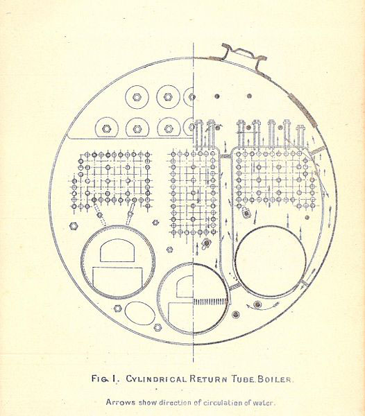
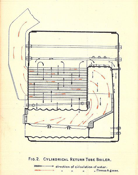
Upon closer examination of the ship’s contract specs we can see that these ships were provided with two Scotch “wet back” boilers that each had three firebox furnaces 38” in diameter. These boilers were 12’ 3” in diameter and 11’ 6” in length and generated 150 pounds of pressure. (Click Images to Enlarge). (Boiler Graphics from The Stokers Manual 1912). |
||
 |
|
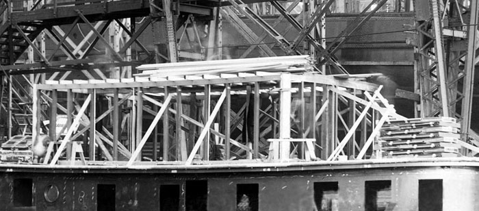
The Mills after launching in the shipway with her superstructure under construction |
 |
 |
|
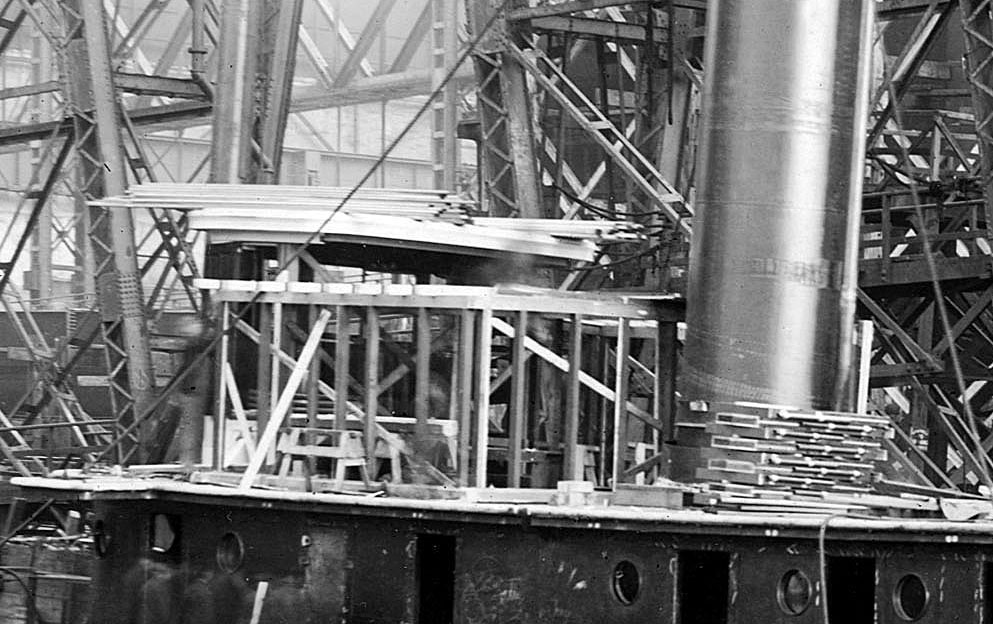
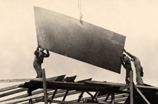
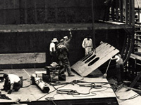
The main deck cabins were constructed of formed steel plates and riveted together, while the upper cabins were framed of Georgia Pine. A stack of window frames is seen on the right. (Click Images to Enlarge). |
|
 |
|
The framing in progress for the upper rear deck stateroom cabins where the ship’s senior officers were berthed. |
 |
 |
|
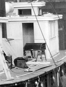
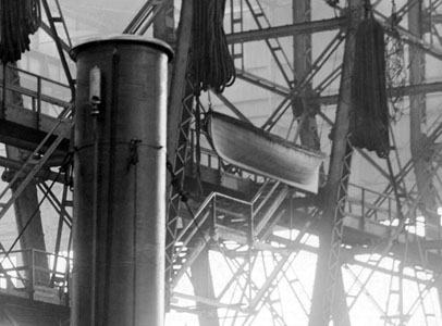
Here we can see a roll-top desk ready for installation in the Masters cabin behind the wheelhouse. A lifeboat is stored up in the cavernous space of the shipway ready for installation. |
|
 |
|
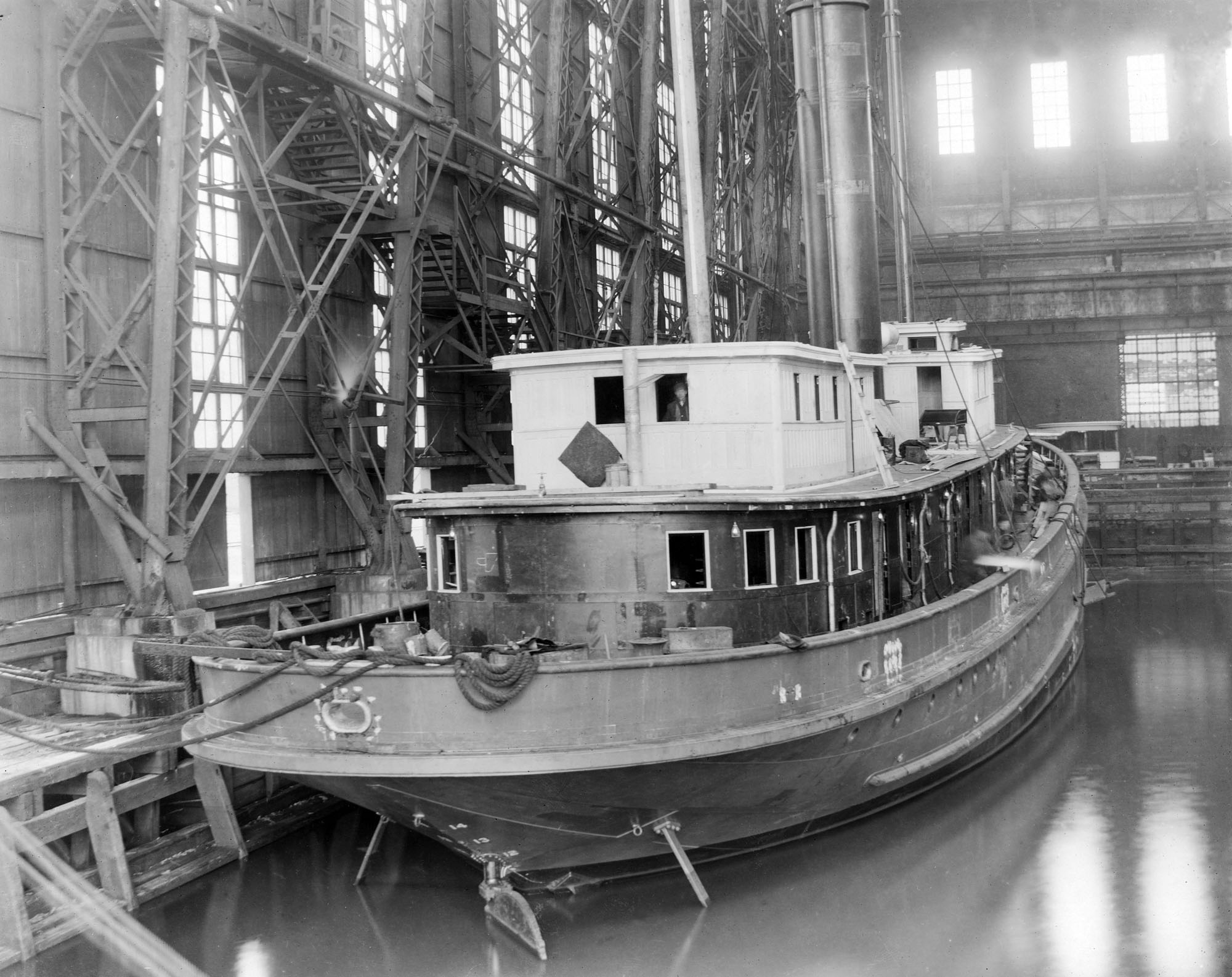
This stern view of the Mills shows the upper cabin woodwork nearing completion as interior construction continues. (Click To Enlarge) |
 |
|
The General Samuel M. Mills in 1909 prior to fitting out, rigging and initial sea trials. This image gives a feeling for the enormity of the Shipway K at the New York Shipbuilding Company. (Click To Enlarge) |
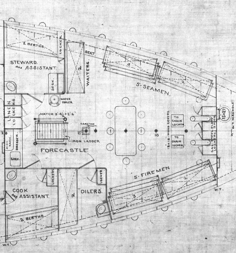
In examining the contract and ship plans it is clear that the Submarine Mine
Service had two separate commands of officers and men aboard these ships.
The ship was run by a crew which consisted of 5 maritime officers, an
engineer and a crew of 18 sailors, while the mine planting mission was
carried out by Army troops which consisted of 3 commissioned artillery
officers, 3 non-commissioned officers, and 18 soldiers. So, as designed,
with a full complement of crew and troops 48 men would be aboard during mine
planting operations, compared to the 66 men aboard Pequot during WWII as
shown on the February 1945 crew list.
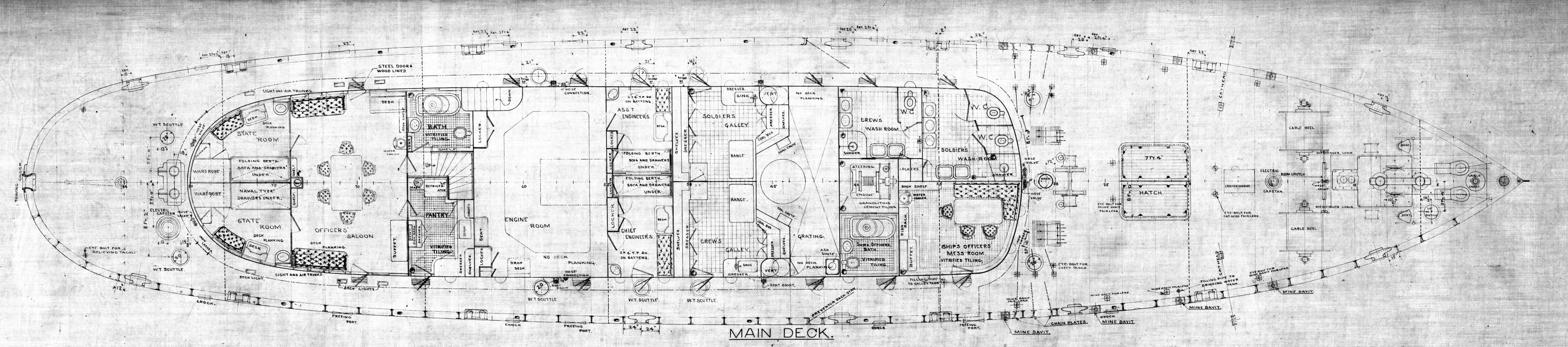 |
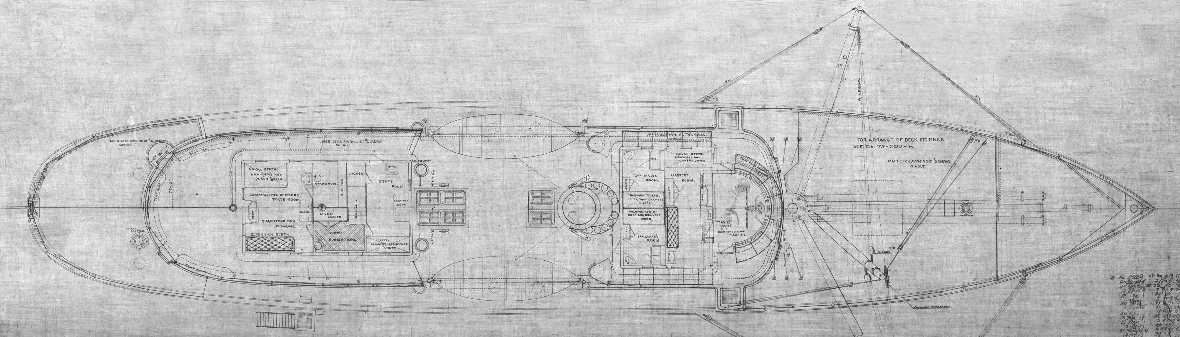
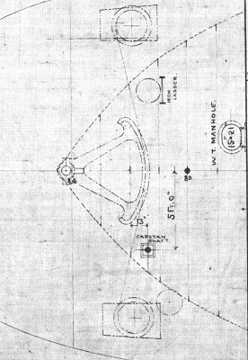
| Main Deck Plan View. Click image to enlarge. |
 |
 |
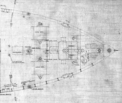
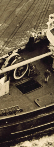
Up on the fo’castle deck we can see the large cable reels used for planting sea mines, air cowls, an electric capstan, lashing stanchions for mooring lines, and the anchor gear.
 |
 |
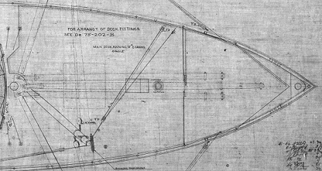
Directly in front
of the forward mast is the ship’s main hatch which is
where sea mines were
brought up from the lower hold and later where Pequot stored thousands of
feet of cable. We also can see the location of the main forward mast,
windlass equipment and a number of eye bolt locations to tie-off rigging
during mine planting operations.
As seen on the right, by the 1940s there was
only one hatch opening after the large cable winch was added.
 |
In the forward cabins
on the main deck we see that the ship’s officers had their own upholstered
dining mess and small galley adjacent to an officer’s bath, and the Army
soldiers had their own washroom separate from the "head" used by the ship’s
sailors.
With the pilot house directly above these cabins, in
the center we see the Steering Engine used to control the ship’s rudder from
the helm above.
Pequot Chief Yeoman
Jim Hudlow writes that in the 1940s, "The enlisted men's mess room was on
the main deck at the place indicated on these plans as the 'Officers Mess
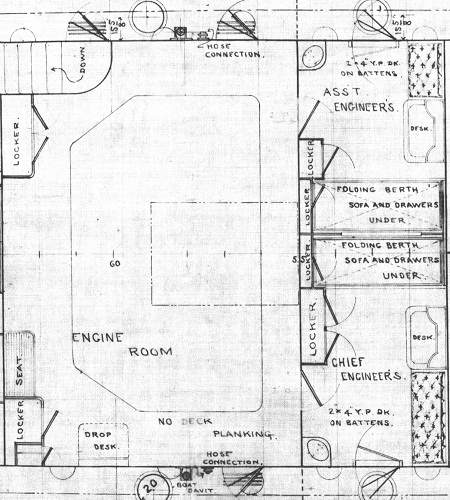
Room'." The two large
reciprocating engines which operated next to the boilers below protruded up
into the main deck’s engine room area.
The catwalk we see around the central opening
was called the Control Deck and it was provided with a desk and work area.
The ship’s Engineer and Assistant Engineer where housed in private
staterooms which opened directly onto this catwalk. We also see on the port
side an exterior doorway and stairs going down to the rear soldier’s
quarters. One can only imagine the noise level in this area.
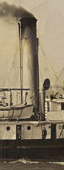
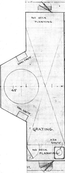
In this photo we can see doors on both sides of the
ship’s stack. The plans reveal that in front of the stack was an
enclosed passageway which provided access from both the port and
starboard side to two vertical chutes used to load coal into the bunkers
in the lower hold near the boilers. (Centre photo -
McCormack Family)
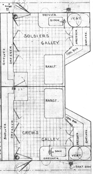
Behind the stack we see that the
ship was built with two completely separate galleys one for the ship’s
crew and one for the Army troops. This reinforces the assumption that
while aboard the Mills these two groups of men must have been fairly
segregated. Pequot seaman Mike Luongo tells us that that the
Pequot had just one Galley that ran the width of the main deck
cabin. A sailor can be seen in the entrance to the galley holding what
looks like a white coffee cup.
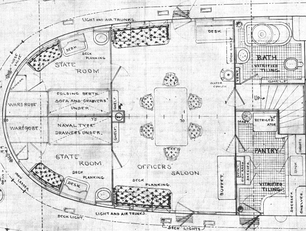
Here
we see that the rear cabins on the main deck were definitely “Officer’s
Country.” Two private staterooms are accessible from a large Officer’s Saloon
which has its own private pantry with a refrigerator and sink. There is also an
officer’s bath and shower which is also accessible from the command officer’s
staterooms above.
According to Seaman Mike Luongo the large "Officer's Saloon" cabin shown
here was used as a mess hall for the Pequot's crew during WWII. This was
the crew's meeting place where they would listen to the radio, play
cards, and write letters. They sat on benches with folding legs that
would be collapsed and stowed on top of the tables so the galley crew
could swab the deck after meals.
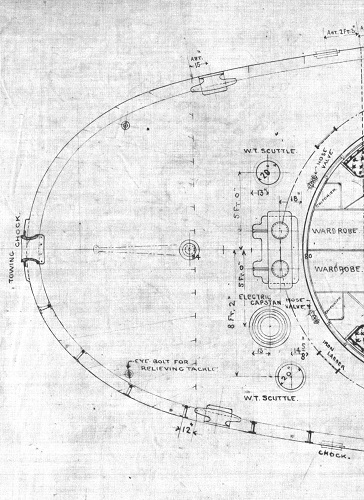
On the stern of the main deck we see the
large bracket or “chock” that could be used if the Mills ever had to tow
another ship. We also see the electric capstan and large stanchions used with
the large mooring lines which secured the ship to its dock while in port.
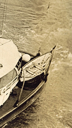
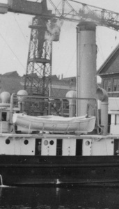
During WWII the small dory, in
which the crew used to set buoy markers when laying
indicator loop cables, was lashed on the stern deck.
(Photo - US Coast Guard Photo).
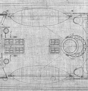
Upper Deck Plan View.
Click
image
to
enlarge.
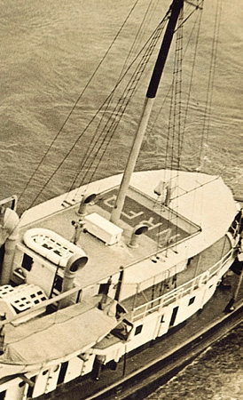
The upper deck plan clearly shows
the stow locations of the three large boom arms on the main mast as well as
the outline of the large forward canvas awning which is seen in this 1933 photo of
Pequot.
(US Coast Guard Photo).
On second deck
level of the cabins containing the pilot house we can see the ship’s helm,
compass binnacle, and port and starboard flying bridges.
This was the business end of ship navigation and
per regulations the ship’s “Master” officer was bunked directly adjacent to
the pilot house.
We also see the 1st and 2nd
Mate were provided with small private staterooms.
By WWII we know that at least one of those
cabins was converted for the Pequot’s radio room,
and Mike Luongo tells us that the other Mate’s Room was the Pequot’s
pharmacy and sick bay. “One New Years Eve about 10 guys got together and we
raided the pharmacy of some 190 proof alcohol and we spiked our Coke’s with
it,” Mike remembers.


(Click to Enlarge)
The curving forward
windows of the pilothouse and the sides of
these cabins were shaded with canvas awnings. It
also looks like a construction foreman’s coffee cup in 1909 may have spilled
over onto this drawing. Pequot Chief Yeoman Jim Hudlow writes,
"The ship's office was on the same level as the pilot house. We had four
office workers and the office was not big enough for all of us." We can
also see that by the 1940s a metal stairway from the fo'castle deck up
to the pilot house and upper forward cabins was added. Those stairs, which
we see in so many Pequot era photos, was not originally built with the ship.
 |
 |
 |
Between the two upper deck cabins was the lifeboat deck where behind the stack two full size lifeboats were always ready and provisioned for emergencies. We also see the skylights over the galleys and engine room below. To the right are the two large air cowls which provided air to the ship’s boilers three decks below.
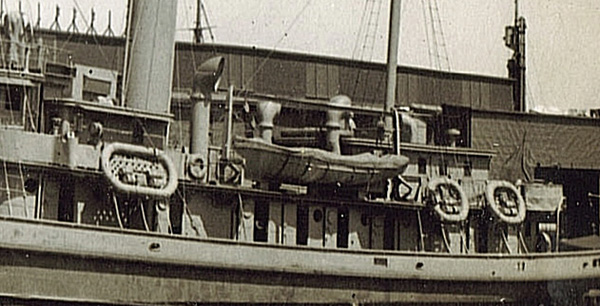 |
During World War II with almost 70 men aboard, in addition to the two main lifeboats, six large web bottom life rafts with provisions were lashed to the Pequot, three on the port, and three on the starboard sides of the ship. Below the rafts we can see the metal guides going down to the gunwale which would be used to slide them into the sea. An additional life raft was lashed to the top of the upper rear deck cabins.
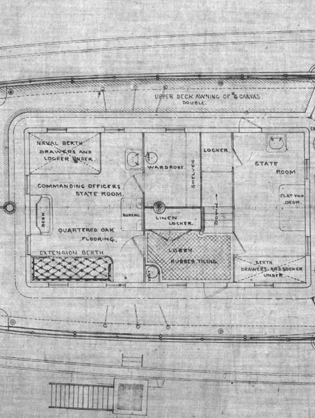 |
In the upper rear cabin we see the Commanding Officer’s stateroom which is accessed from a small lobby area which also leads to a second ample state room most likely for the command officer of the Army troops. The ship’s captain was provided a full size bed, sink, desk, bureau of drawers and an upholstered couch which could double as a 2nd berth. Private stairs from these two staterooms lead down to the officer’s bath below.
 |
 |
Both sides of this cabin and the fantail deck behind it were covered by a canvas awning. During WWII the awning was removed and this upper rear deck held the two 20mm Oerlikon anti-aircraft guns and ammunition ready boxes. (US Coast Guard Photo).
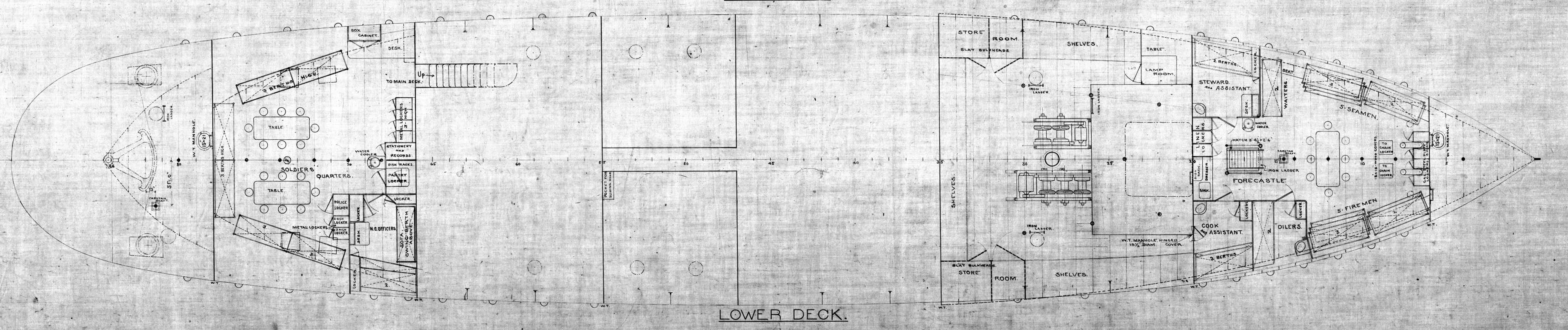 |
| Lower Deck Plan View. Click image to enlarge. |
 |
 |
| (Click to enlarge) |
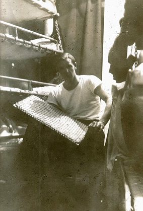 |
In the only WWII era photo we have of the crew quarters we
see on both sides of George Simmons that bunks are stacked 4 high, about 30"
apart and that the space between the row of berths looks about 3' wide.
Seaman Mike Luongo remembers that "The main
crew sleeping quarters was in the forward part of the ship. It had bunks 4
high with 4 rows on one side and 4 on the other." Jim Hudlow,
Pequot Chief Yeoman writes, "The
enlisted men's living quarters was on the lower deck up forward. There was a
small walled section in this area for Chief Petty Officers. I had a bunk in
the chief's section." Mike Luongo adds, “Yea, we slept four high
and it was all based upon seniority. When you first came aboard you got the
last bunk in the back by the maintenance room and carpenter's shop. That’s
where the cold air from outside came down into the hold. Whenever some guy
got transferred everybody would move. We’d wrap our mattress around our
seabag and shift bunks. The best spot was the top bunk all the way forward
up at the bow. I eventually ended up there!” (Mike Luongo photo).
 |
Behind the rear fo’castle bulkhead was the ship’s main hold where sea mines were stored. Here we see the motorized port and starboard drums on both sides of the main forward mast which controlled the three large boom arms used during mine planting operations and to hoist deadly sea mines up to the fo’castle deck above. Against both sides of the hull we see other storage areas which were probably used to stow gear and expendables. After conversion to a cable ship this area was modified to serve as the Pequot’s large cable hold.
 |
| (Click to enlarge) |
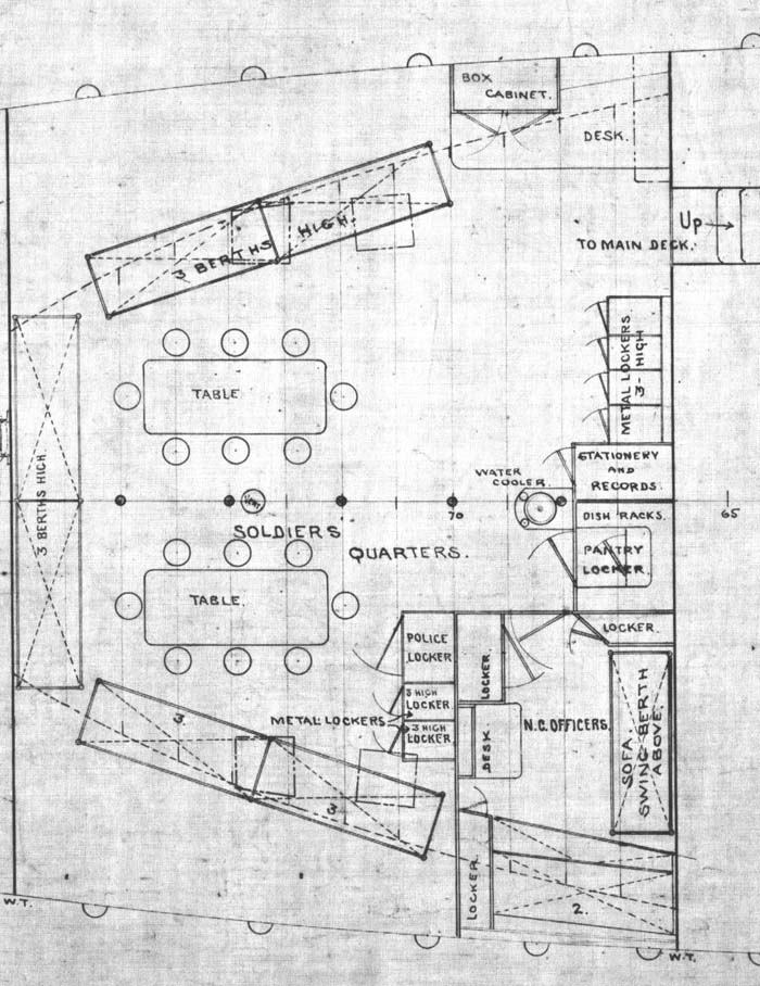
The aft end of the lower deck was designed as the
Soldiers quarters for the Army Troops. Here we see a small private
compartment for non-commissioned officers with two berths against the hull
and one berth as a swinging hammock above a sofa.
Two tables with chairs, a water cooler, sink,
and small pantry are provided along with what appears to be lockers for
small arms.
Based upon the number of berths shown this area
was designed to sleep 21 soldiers.
 |
Aft of
the Soldiers Quarters we see details of the two capstans that operated
the Steering Quadrant which controlled the ship’s rudder from the
forward steering engine.
 |
| Lower Hold Plan View. Click image to enlarge. |
Mike Luongo tells us that in addition to cable, in the large hold between the engine room and the forward crew quarters there was a carpenters shop and storage for cleaning supplies. “That’s also were they kept everything we used on painting duty. We had chipping hammers, paint, brushes and scrapers.”
 |
In the far forward lower hold we see the lockers for
the ship’s two anchor chains, large refrigerated storage coolers as well as
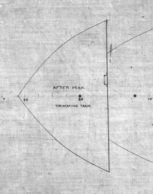
other food storage compartments. A trimming tank is seen far forward which
could be filled with sea water as needed if the ship was too light at the bow.
Seaman Mike Luongo explains that, “Whenever we went out to sea they made
sure we had enough supplies and they were all stored down below. We formed
a human chain gang down through the fo’castle to the refrigerators down
there to stock up. We also had a freezer for frozen food and meats. We
always had enough provisions for at least two weeks at sea.”
 |
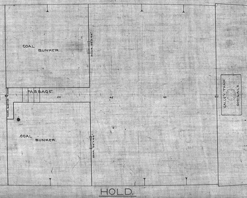 |
Although these plans do not provide
details on the placement of the ship’s boilers and engines, here we see two
large coal bunkers which could hold 128 tons of coal and the location of the 600
gallon fresh water tank which would weigh 5010 lbs or 2.5 tons when full. When
we include the 2-3 tons of cable that could be stored in the forward hold and
other supplies, when the Pequot left port she had close to 135 tons of
expendables aboard. In addition to the trim tank at the bow we see that a rear
or “After Peak” trimming tank was located at the stern. These fore and aft
trimming tanks would be filled with seawater as needed to keep the ship riding
level at sea. As coal was burned, water was consumed, and cable was laid, weight
would be reduced in different sections of the lower hold and by adding or
draining water from these tanks the ship’s trim could be kept in balance. Mike
Luongo tells us that water was rationed. “When we were out at sea we could only
take a shower every third day. When we were in port you could have a shower any
time you wanted to.”
 |
 |
|
One of the "General" Army mine planters preparing to lower a mine into the sea, possibly the Mills. Here we can clearly see the three large forward booms off the main mast in use during this delicate operation. (Photo courtesy Ramon Jackson from the Coast Artillery Journal, May 1926) |
A sea mine of the era being hoisted on davits ready for planting by an Army mine planter. (Coast Defense Study Group, Inc.). |
 |
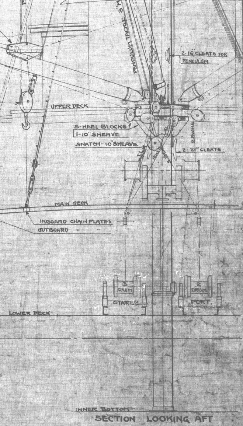 |
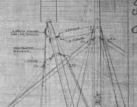
|
This elevation shows the complex articulation of the three booms
and the extensive rigging
required for mine planting operations.
(Click to Enlarge). |
The main mast ran down to
the lower hold and attached to the top of the keel. (Click to enlarge). |
 |
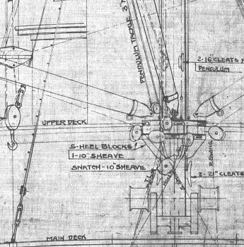 |
As seen in these details the operation of the three boom arms required very sophisticated rope and pulley rigging as well as the use of motorized winch drums on the upper and lower decks.
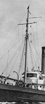
The Changing Masts
Over the years the ship’s forward mast was completely re-configured a number
of times based upon mission needs as an Army mine planter and a Coast Guard
cable layer. In addition to rigging and rope ladders many of the lines we see on
the ship’s mast were antennas for the various generations of short and long wave
radio transmitters and receivers installed as communication technology advanced.
 |
 |
 |
 |
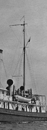
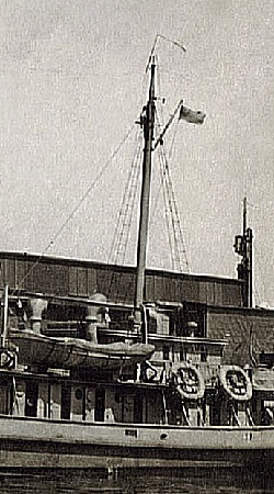
| 1909 | 1927 | 1943 | 1944 - 1947 |
|
(Photos Left to Right - US Naval Institute, US Coast Guard, Calamaio Family, Lou Carhart) |
|||
When originally constructed as an Army mine planter the ship had three large forward booms and there was no yard arm on the forward mast. The rope and cable ladders, or “rat lines,” crew members could climb up were installed on the port and starboard sides to permit servicing of the pulley and rigging system needed for the forward booms.
By 1927, after conversion to a cable ship in 1922, two of the large forward booms were removed, additional running lights were added, and an upper yard arm was installed near the top of the mast for radio antennas. It appears the height of the mast was increased and a cross member for radio antenna wires which ran to the rear mast was suspended by cables behind the forward mast. In addition to mast mounted lights three vertical cable work indicator lights or pendants are seen suspended from the upper yard arm. By 1943 those units are no longer present and the radio antenna cross member has been removed during WWII. We see in the May 1944 photos of Pequot, that the ship’s mast was reduced in size and a longer yard arm was installed to accommodate the newest generation of radio and radar antennas.
 |
 |
 |
| 1909 | 1927 | May 1944 |
|
(Photos Left to Right – Independence Seaport Museum, US Coast Guard, Lou Carhart) |
||
|
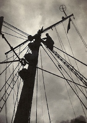
“It is requested that the Navy Yard, Boston, remove topmast of PEQUOT mainmast together with shortstays, etcetera, this to include the reducing in size of the jackstaff. In removing the topmast it is also requested that the radio antenna be installed at the highest possible point between the fore and mainmast.” |
 |
 |
|
A WWII Pequot sailor up on the ratlines servicing the running lights and a profile of the rear mast before the 1942 reductions. (Both McCormack Family) |
|
 |
This cross section detail shows the ship's
keel and the honeycomb
design of the ship's strong double bottom
hull.
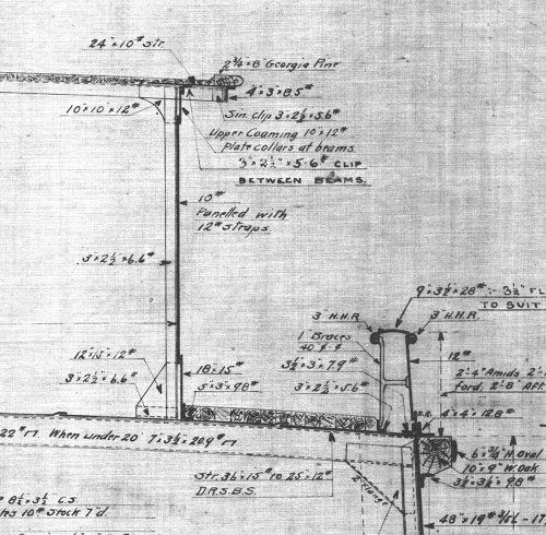 |
Here we see the wooden decking and a cross section of the gunwale which rose 28" amidships.
Go to Part Two to learn more about five of the Pequot’s “Sister Ships” and their construction Click here
 |
 |
 |
|
Joyner Library Special Collections, East Carolina University |
||
Special Thanks to Ramon Jackson.
For more information on the history of the Coast Artillery Corps and the Army
Mine Planter Service see:
http://patriot.net/~eastlnd2/army-amps.htm
Special Thanks also to Matt Herbison at the Independence Seaport Museum for locating these construction photos for us.
Every effort has been made to trace and acknowledge copyright. The authors would welcome any information from people who believe their photos have been used without due credit. Some photos have been retouched to remove imperfections but otherwise they are true to the original.
FEEDBACK
If you have comments or queries specifically
about the Pequot or her Sister Ships, please contact
Chip Calamaio
chipaz@cox.net, 938 E. San Miguel Avenue, Phoenix, 85014, Arizona,
USA. (H) 602-279-4505.
Click here to go to the Pequot Main Page.
Research and design: Chip Calamaio and Richard Walding