USCG CABLE SHIP PEQUOT - UNITED STATES HARBOR DEFENCES
| The Pequot's Navigation and Magnetic Deviation Systems |
These pages tell the story of the U.S. Coast Guard Cable ship Pequot during World War II as a harbor defense cable-laying and repair ship under direction of the US Navy. This site presents details of the ship's navigation and magnetic deviation systems in use during the laying anti-submarine indicator loop cables. During the 35 years that the USCG Pequot was at sea, navigation was accomplished through the use of nautical charts and compass readings.
 |
|
 |
|
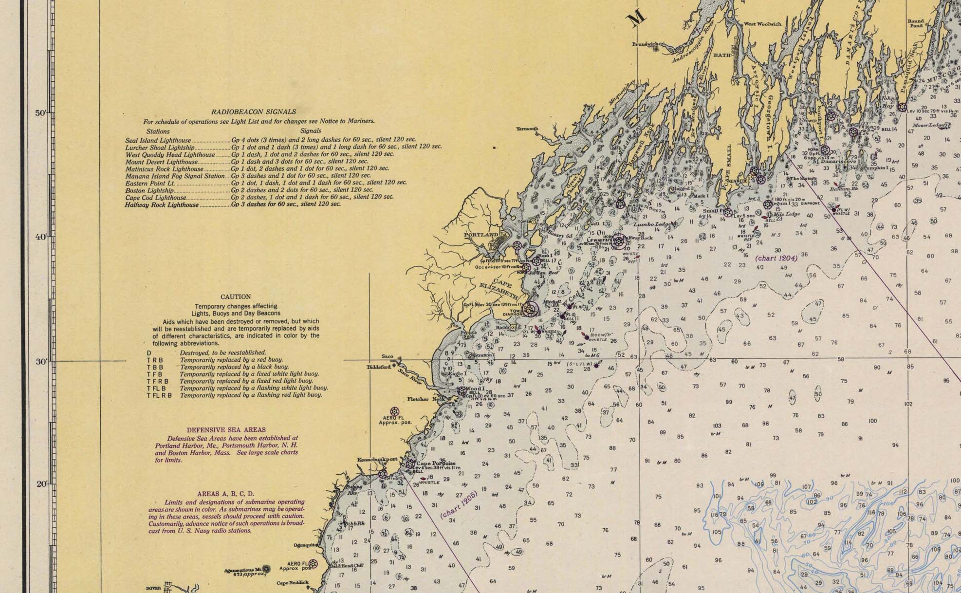
Nautical Chart: When steaming along the rocky
coast of Maine during WWII the Pequot’s navigator
and captain would use the ship’s compass and a
nautical chart such as this one from 1944. A
close-up on the right shows numbers in the ocean
which indicates the depth of water in fathoms,
with one fathom equal to 6 feet. (US Coast and
Geodetic Survey 1944) Click image to enlarge. |
A section of the
Nautical Chart Abbreviations used with the
charts opposite. (US Coast and Geodetic Survey
January 1941) Click image to see a full sized view. |
|
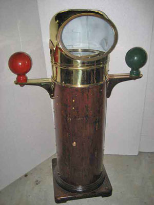
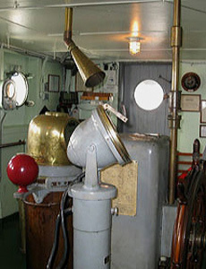
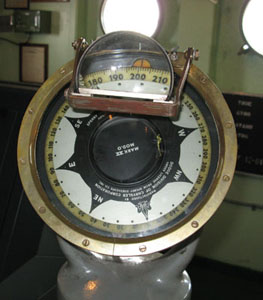
Binnacle:
During the 1940s directly in front of the helm in the
pilothouse was a John E. Hand & Sons 8" liquid
Compensating Pedestal Type Spherical Compass Binnacle.
This was the ship's primary navigation compass when
she first went to sea.
 |
 |
|
118. We can see the placement of the steering binnacle in the pilot house on the 1908 construction plans. |
119. A typical Compass binnacle of the period with red and green iron spheres (quadrantal spheres) used for magnetic deviation adjustments. (Antiques of the Sea, Lionel Corporation Binnacle 1944) |
The "binnacle" is a watertight stand which holds the ship's magnetic compass. It is designed to be seen by a helmsman standing at the ship's wheel. Consisting of a circular base, a pedestal, a magnet compartment, and a chamber where the compass 'floats' in a metal ring in a bowl of alcohol on two pivots, the binnacle's gimbals keeps the compass level despite the motion of the ship. Early binnacles had a small oil lamp mounted on one side of the compass for night viewing. Electric lighting systems were introduced later.
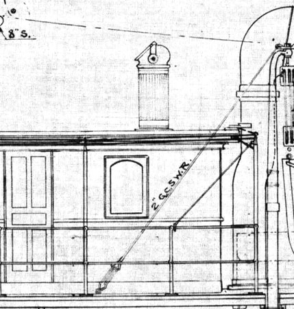
Mounted 21' above the Pequot's main deck and 60' from the stern the "After Deck House" Compass on Pequot was an E. S. Ritchie and Sons 8" liquid Type 7, (#49 U.S. Navy Bureau of Navigation Machinery Division) Compass Binnacle that had been on the ship since January of 1919. This "back-up" compass was located on top of the rear deck cabins so it would be as far away from the magnetic signature of the steel hull as practical.
 |
 |
|
120. The After Deck House compass binnacle is clearly detailed in the 1908 elevation construction drawings. |
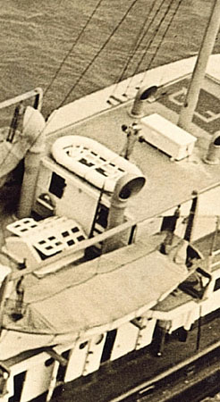
121. Just aft of a life raft on top of the officer's staterooms we can see the exterior compass binnacle with its distinctive iron adjustment spheres. (Calamaio Family) |
These critical navigation compass binnacles were periodically re-calibrated to compensate for the difference or "deviation" of true north from magnetic north, and adjusted for the magnetic influence of the ship's steel hull. Changes in the magnetic signature of the hull after deperming and degaussing during WWII only complicated matters.
Captain Matthew Flinders of the Royal Navy, determined that erecting a vertical metal bar in front of the compass allowed adjustments to be made for magnetic deviation. Those bars were named Flinders Bars in his honor. Later, Sir George Airy, the Astronomer Royal, discovered that the accuracy of the magnetic compass could be further improved by placing quadrantal spheres (large balls of soft iron) on either side of the compass. Both the Flinders Bar and the quadrantal spheres, along with various adjustable compensating magnets, for correcting the compass were part of the Pequot's compass binnacles.
 |
 |
|
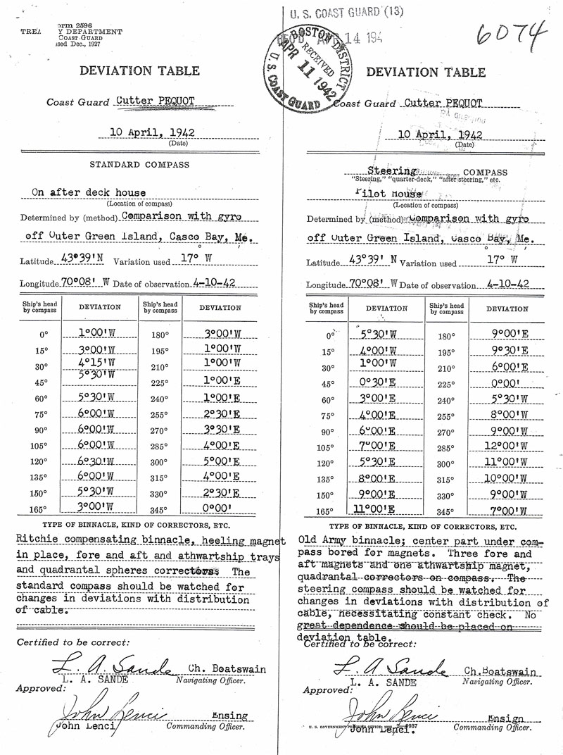
122.
An April 10th 1942 Deviation Table shows
adjustments were made to correct for 17 Degrees of
deviation. At that time Lars Sande was the ship's Navigation
Officer. The commanding officer was Ensign John
Lenci.
(National Archives and Records Administration,
Records Group 26 Entry 26C) |
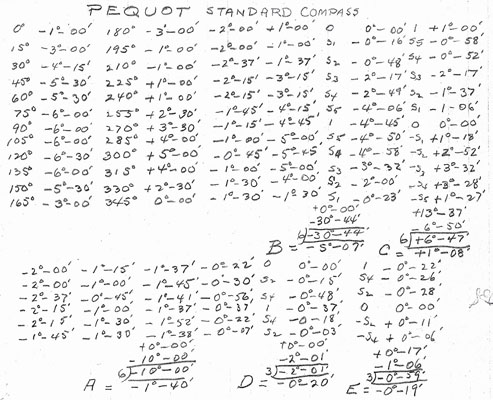
123.
The methodical hand calculations required during
the April 10th 1942 compass calibrations. (National Archives and Records Administration, Records Group 26 Entry 26C) |
We see that the April 1942 compass calculations took place at sea off the coast of Maine near Outer Green Island which is one of the many islands of Casco Bay. The notes from the Coast Guard District Compass Adjuster tell us that the Pequot’s gyrocompass was used as the reference during the calibrations. The Compass Adjuster pointed out that laying the metal cable from the Pequot’s hold could cause magnetic deviations and effect the accuracy of the binnacle. “The steering compass should be watched for changes in deviations with distribution of cable, necessitating constant check. No great dependence should be placed on deviation table.” This reinforces how critical the Pequot’s gyrocompass was to accurate navigation of the ship.
 |
 |
|
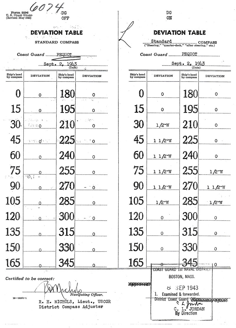
124.
The records of Pequot's
September 2nd 1943 compass deviation adjustments note
that the ship did not have a Degaussing Coil installed.
Yet at the top of the Deviation Table column notations
for the Standard Compass we see references to "DG OFF"
and "DG ON". DG stood for Degaussing. (National Archives and Records Administration, Records Group 26 Entry 26C) Click to Enlarge. |
|
Gyrocompass:
In addition to the main compass
binnacle, during WWII the Pequot's pilothouse was also
equipped with a Gyrocompass, which was invented in 1908
the year the ship was built. A Gyroscopic Compass uses
a spinning gyroscope which, once calibrated, keeps the
compass pointing not to the magnetic north, but to the
Earth's true North. Once the rapidly spinning gyroscope
inside the compass is set spinning, it remains pointing
in the same direction, regardless of the ship's motion
at sea.
 |
 |
 |
|
125. In one of the few photos we have inside the Pequot's pilothouse, we can see a gyrocompass with a magnifier for the Quartermaster similar to the one on the bridge of the 1945 Victory Ship S. S. Lane Victory (V-794). (Centre photo courtesy Mike Luongo; left and right images www.lanevictory.org/index.php) |
||
 |
 |
|
126. Pequot Quartermaster Ozzie Frontel keeps a keen eye on the gyrocompass. (Mike Luongo) |
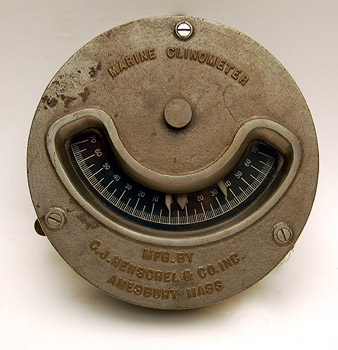
127.
A Marine Clinometer of the era. (Maine Maritime Museum) |
In addition to the standing compass binnacle and the
newer gyrocompass, Quartermasters in the Pequot's wheel
house also used the ship's wheel which was hydraulically
connected to the steering engine, a Rudder Indicator
which let them know what angle the rudder was set at, an
RPM gauge which showed the revolutions per minute of the
two propeller shafts, a Fathometer to let them see the
depth of water beneath the keel, and a Clinometer which
indicated the degree of roll the ship was under which
was critical in rough weather.
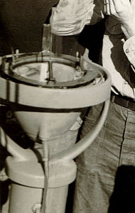
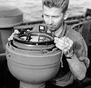
Pelorus: Both the port and starboard
side flying bridges on Pequot were equipped with
a pedestal mounted gyro-compass repeater that duplicated
the direction reading indicated by the main gyrocompass
in the wheelhouse through electrical signals. To take
bearings on objects outside the ship, a Pelorus with
movable sighting vanes was mounted on top of these
compass repeaters to enable the ship’s navigator to
obtain direct bearings of objects which could aid in
navigation such as a distinctive land form or a
lighthouse. True bearings were read by observing the
degree on the compass card that the crossbar of the
sighting vane lined up with. Relative bearings could be
read from an outer dumb compass ring on the repeater
stand.
 |
 |
 |
| 128. One of the Pequot’s pedestal mounted gyrocompass repeaters with Pelorus in place. Note the electrical cable which connects this compass to the main gyro-compass on the bridge. (Mike Luongo) | 129. Quartermaster 1st
Class Chester I. Isaacson taking a reading with
a Pelorus on the Destroyer Escort USS Hilbert
(DE-72) during WWII.
(George D. McCarthy) |
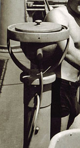
130. When not in use
the Pelorus was removed and the compass was
covered to protect it from the elements. (Calamaio Family) |
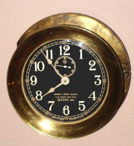
To accurately determine the Pequot’s position, the standard formula of time at speed equals distance was used to calibrate how far the ship had traveled on a given bearing. Early binnacles included a sand timer similar to an hourglass. By the 1940s highly accurate ship clocks were the standard in every wheelhouse.
 |
|
| 131. A
1940s US Navy Bureau of Navigation Mark I deck clock. (Savage and Polite’s Antique Clocks) |
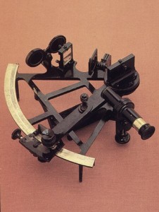
132.
Referred to as Celestial Navigation, a sextant
enables ships at sea to determine their location
by ‘fixing” their position from the sun, the moon,
a planet, or a star and their angle above the
visible horizon at certain times of the day or
night. (NOAA photo) |
Quartermaster Lou Carhart tells us that the Pequot’s
officers were responsible for all navigation
calculations, plotting the ship’s course and maintaining
the deck log entries. Quartermasters assisted with
taking star or sun sightings off the horizon using a
sextant, but primarily were responsible for keeping
their attention focused on the bridge gyrocompass and
keeping the ship on a given bearing.
Ship navigation was, and continues to be, a very
complicated science where a number of elements all must
be factored in using a variety of calculations and tools
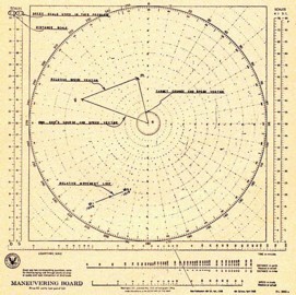
such as the use of a Maneuvering Board which is used for
solving relative motion problems. Bearing and distance
marks from the center of the board and scales at the
sides, allow quick and easy plotting of course and speed
vectors to quickly determine and calculate a course
bearing and a speed in knots to intercept, or avoid,
another vessel.
 |
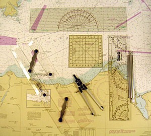 |
| 133. The Maneuvring Board was first established in 1920. It uses a polar coordinate system that is divided into 360 units or degrees and a series of concentric circles which relate to speed in knots. Scales on the side of the diagram can be used to determine relative or actual speed and distance. (Defense Mapping Agency) | 134. Various rulers, dividers, protractors, and other plotting tools were used with the Pequot’s nautical charts to calculate navigation solutions. Here we see a modern navigator’s “tool pack” using the same devices common on the Pequot more than 65 years ago. (Starpath Corp.) |
Pequot Quartermasters Carhart, Simmons, Livingston and others all went through extensive training to obtain their rating where they had to learn that a ship’s speed was measured in knots which equal 1.151 nautical miles per hour, and that a nautical mile was equal to 1.15 statute miles on land. Most importantly they had to gain the skills to handle the ship’s wheel and be able to respond to cross winds, heavy seas, and the techniques required for tight maneuvering especially during cable laying operations.
Even though today satellite generated GPS signals are used extensively for maritime navigation, ships still routinely use compass bearings and the earth's magnetism to set their course.
Every effort has been made to trace and acknowledge copyright. The authors would welcome any information from people who believe their photos have been used without due credit. Some photos have been retouched to remove imperfections but otherwise they are true to the original.
FEEDBACK
If you have comments or queries specifically
about the Pequot or her Escort Ships, please contact
Chip Calamaio
chipaz@cox.net, Phoenix, Arizona,
USA. (H) 602-279-4505.
Click here to go to the Pequot Main Page.
Research and design: Chip Calamaio and Richard Walding