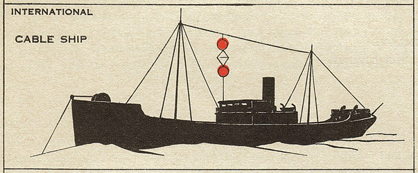
USCG CABLE SHIP PEQUOT - UNITED STATES HARBOR DEFENCES
The Pequot's Communication and the Radio War
|
 |
|
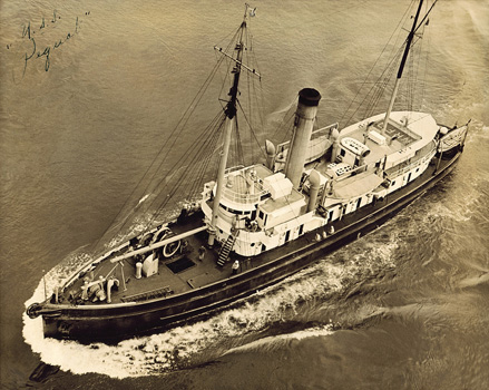
The US Coast Guard Pequot. During WWII this cable ship laid top secret Indicator Loop cables to protect harbors from German U-boats. Her mission ranged from the ports of Virginia up to Argentia, Newfoundland. (Calamaio family). |
COMMUNICATIONS
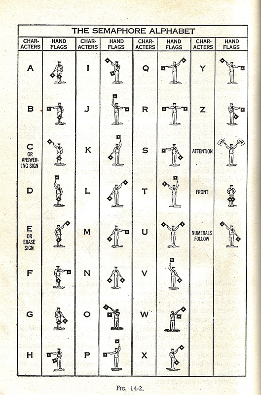
The images below show sailors using semaphore and Morse. As well, thumbnail images of pages from the 1940 Bluejacket's Manual are shown. Click these "Bluejacket" images to see an enlarged view. Note: In the enlarged view of the Communication Training chart below, you will see handwritten notes by Sailor Roger Calamaio. We can speculate that his updates to the code alphabet, from bootcamp in 1942, may have been made, by the military, to confuse the enemy. Although still in use, in the 65 years since the Pequot sailed, the Military Code Alphabet has changed. For example, today A is Alpha and Z is Zulu.
 |
 |
 |
 |
 |
|
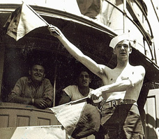
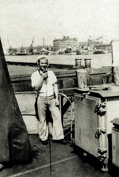
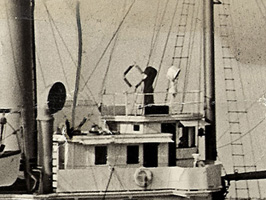
57. Visual Communication was achieved using semaphore
flags. Pequot 1944 |
58. Morse Code was used with the
highly directional blinker light. Pequot 1944 |
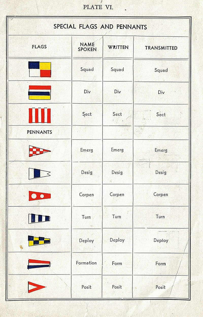
59. Flags & Pennants from 1940 Bluejacket's Manual. Click to enlarge. | 60. Communication
Training 1940 Bluejacket's Manual.
Click to enlarge. |
61. Semaphore Alphabet
1940 Bluejacket's Manual. Click to enlarge. |
The Pequot's Visual Call Sign was W-58 which meant that the W,
5, and 8 flags would be flown from the mast to identify her to other
ships.
 |
|
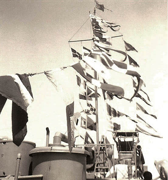
The signal flag storage box on Coast Guard Patrol Boat CG-94001 which served as one of the Pequot's escort ships in 1943. In addition to letters and numbers we see the symbols of special communications flags and triangular pennants which were used to signal maneuvers like turns, formation, and deployment. (courtesy Paul A. Schlais Family) |
 |
|
Signal flags snapping in the breeze on Patrol Boat CG-94001 with the Coast Guard Ensign flying on the mast. The ship's long thin "Commission Pennant" is also tied off on top of the mast. (courtesy Paul A. Schlais Family) |
Running Lights and Pennants
 |
|
|
|
|
|
(color added) |
(USCG Nautical Rules of the Road 1943, Page 115) |

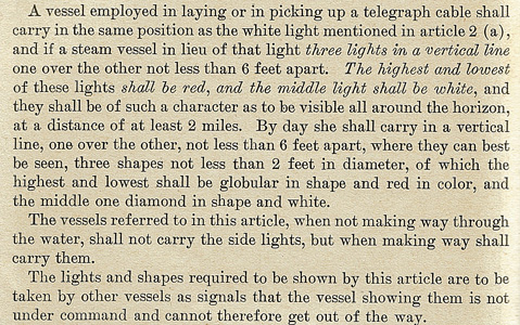
In addition to having the universal Red to Port and
Green to Starboard running lights, as a cable ship operating in international
waters, the running lights added to Pequot's mast consisted of an upper and
lower red light with a while light in the middle. Per the regulations detailed
in the Coast Guard's 1943 "Nautical Rules of the Road" directives
when Pequot was stationary and not underway the standard red and green
side running lights were to be turned off as a signal to other ships that Pequot
was not under power and unable to get out of the way.
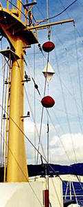
For cable ships
in international waters during daylight hours of operations two round red balls
separated by a white diamond pennant are flown from the ship's mast which tells
other vessels: "Keep clear I'm engaged in underwater operations".
Despite these "road rules"
we can assume that during much of her WWII travels along the Eastern seaboard,
especially at night, that Pequot ran dark to avoid detection by U-boats. (color added).
The CS Alert 1966
(Atlantic-Cable.com Although primitive by today's standards radio communications of many
types played an intense role during WWII especially in the Battle of
The Atlantic. Like all Coast Guard ships, the Pequot was equipped
with a variety of high and low frequency radio receivers and
transmitters. Most radio traffic was enciphered. The messages came
in 5-character groups of numbers and letters mixed together.
Radiomen had no idea what they were receiving. Transcriptions would
be passed to an officer on the bridge who would do the decoding.
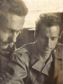
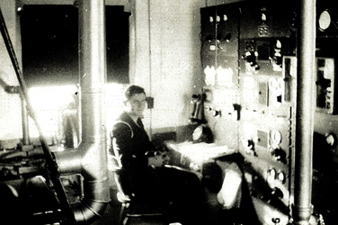
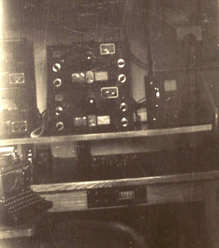
62. Pequot Radioman 1st Class
John J. McCormack with Lester Jenkins in the Pequot's Radio
Room" 63. In Boston Harbor
Wallace Hoganson tests the intercom system by one of the tarp
covered 20mm cannons. A large ammunition ready-box is on the
right. The Mill. All communication had to be accurately documented and logged
and a custom communications typewriter called a "mill" was used by most
Radiomen. It had special keys to distinguish between similar characters such
as the numeral 0 and the letter O. The mill had a slashed zero "Ø" so there
was no confusion with a capital O, It also had a #1 key, which other
typewriters of the era didn't, a small "l" was normally used. The mill was
designed to eliminate having to use the shift key as much as possible for
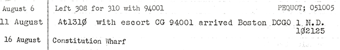
speedy radio transcription. 64. As evidenced by the slashed zeros, this 1944 radio log entry of
the Pequot's movements was typed with a mill. It notates that on
August 11th at 1310 hours (1:10 pm) the Pequot arrived at
the District Coast Guard Office of the 1st Naval District in
Boston escorted by the CG-94001. (US Coast
Guard History Office) For much of the time radio silence was the rule so ships
like the Pequot relied extensively on coded inbound communication from shore
stations. There were also codes inside codes; for example "Z-codes" were used
as abbreviations for longer routine messages. For example; ZEQ = How is my note? ZET = Your transmitter is not keying properly.
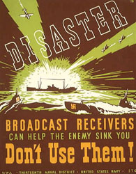
66.
The Navy worked to let convoy
ships know how U-boats could find their position by picking up
radio transmissions.
When at sea short range two-way voice radio was permitted
using a the Talk Between Ships, or TBS system. This was only permitted when
ships were in very close proximity to each other. At night, when visibility
was greatly reduced, and when submarines or other enemy vessels might be
within range, use of very high Frequency or VHF radio was strongly
discouraged. There were many cases where the German U-boats and surface
ships would try to bait Coast Guard and Navy convoy escorts by sending out
false distress calls. Other basic communication was also completed by the
dash and dot alphabet of Morse Code by tapping hand transmitters. Coast
Guard Radiomen had to be expert at notating incoming Morse Code
transmissions quickly and accurately. Lives often depended on correctly
receiving the distress calls from cargo ships after U-boat torpedo attacks
on the Eastbound and Westbound convoys. The Pequot's Radio Call sign NRFQ
was designated by the Office of Naval Operations for all US Navy and Coast
Guard ships. In addition the Pequot was equipped with its own intercom
communication system that was used between the bridge and the ship's main
operational areas such as the engine room, the radio room, and the two rear
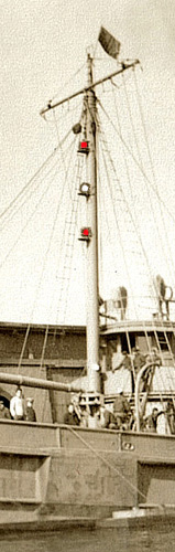
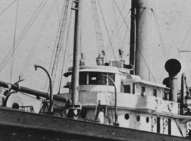
mounted gun positions. Radio Direction Finding. Shortly after the Army mine layer
General
Samuel M. Mills was converted to the cable laying ship Pequot she was
equipped with a first generation radio direction finding (RDF) system or
Radio Compass. This
can be seen on the photo below (right) as the distinctive diamond shaped
rotating antenna on top of the wheelhouse. It is not evident on the earlier
photo to the left. This
technology, which was first deployed by the Coast Guard in the early 1920s,
enabled the ship's radio operator to get a compass bearing fix on the source
of a ship or shore radio transmission. Not only was this an aid to
navigation, but it enabled ships to locate each other at sea and during the
war determine friend from foe.
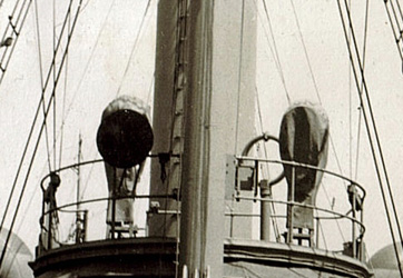
68. This close up of the General Samuel M. Mills shows that no RDF system was
installed before the Coast Guard obtained the ship. 69. From the early 1920s until midway through WWII the
Pequot was equipped with the diamond shaped antenna of early
RDF systems.
(McCormack Family) HD/DF or Huff-Duff. We see that by 1944 the diamond shaped RDF antenna was replaced by a circular loop antenna
(see left-most photo below). This indicates that
Pequot was equipped with the newly developed High Frequency Direction Finder
(HF/DF) system or Huff-Duff as crews liked to call it. This new system was
vastly superior and more accurate than earlier systems and enabled Pequot to
not only obtain bearings from shore stations and more accurately navigate
the rocky North Atlantic coast, but also to locate other Coast Guard and
allied ships, as well help keep a keen ear out for transmissions from
U-boats. Radio direction finders and Huff Duff technology were used
extensively by both the German U-boat commanders and the ships of Allied
convoys during the battle of the Atlantic. Each side did all they could to
locate the position of their adversaries radio transmissions. The Germans
used RDF to locate convoys and moved U-boats into position for torpedo
attacks, and Allied escort ships used Huff Duff readings to set course
bearings to chase down and depth charge wolf pack submarines.
A June 7th
1942 "Request for Work Authorization" we've obtained from National Archives
signed by the Chief of the Coast Guard Radio Engineering Section, Irving L.
Gill instructs the First Naval District Boston Radio Engineering Maintenance
group to "Remove present CGR-17-B direction finder and install a Direction
Finder (DF) Type RDSC-121 complete with gyro-repeater." We believe this
equipment change was the Huff-Duff technical upgrade we see evidenced in the
WWII era photos of Pequot.
70.
This photo from May of 1944 clearly shows the installation
of the circular loop antenna of the improved "Huff-Duff" radio
direction finding system.
(Calamaio family) SO-1 Detection Radar. At the beginning of
World War II radar was an emerging technology. In the late 1930s the
first generation of ship borne CXAM radar was deployed on US and British
battleships and aircraft carriers. In 1940, a group of British
researchers stumbled upon a new electronic component, the "cavity
magnetron," a type of transmitter tube that permitted the development of
effective microwave radar. In America, Bell Labs, RCA, and Westinghouse
explored and developed a wide range of radar technologies before Pearl
Harbor, and a primary research and development center, the Radiation Lab
at the Massachusetts Institute of Technology, was created in 1940. With
the outbreak of war the MIT "RadLab" greatly stepped up research work as
did a large number of British efforts including those led by Reginald V.
Jones in what was dubbed "The Wizard War". By 1942, new radars were
coming into service on both sides of the Atlantic and being deployed on
ships, planes, and land based stations. Half of the radar deployed
during World War II were designed at the MIT RadLab, including over 100
different radar systems costing $1.5 billion.
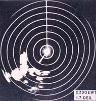
71A. A 1945 Radar Plan
Position Indicator or "PPI" Scope.
(serialconsign.com) 71B. SO-1
Operator Controls.
(From the April 1945 Radar Operator's Manual)
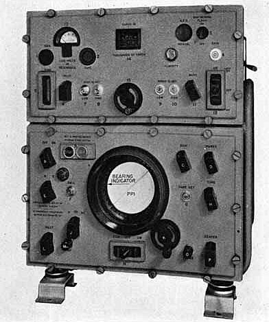
In 1945 the Pequot was equipped with SO-1 microwave
search radar which had a maximum reliable range of 13.5 miles to see
aircraft at 500' elevation, it could see a battleship at 23 miles, and a
destroyer at 14 miles, but it could only distinguish a surfaced
submarine at a range of 1 mile. It had a resolution of 200 yards and at
4 miles was accurate to about 60 yards. It enabled Pequot to see ships, planes and coastlines
in all types of weather and at night through the use of a Plan Position
Indicator (or PPI) scope. Contacts picked up on the PPI scope would
immediately provide officers on the Pequot's bridge the range and
bearing of aircraft and ships in the area, as well as verify Pequot's
location along the rocky shores of New England, Nova Scotia and
Newfoundland. Although a short range device, the addition of SO-1 helped
Pequot see in the dark and greatly increased the ship's safety.

(Calamaio family)
(USCG "Nautical Rules of the Road" 1943
Page 82)
The Radio War
(McCormack family)
(Freiermuth family)
(Freiermuth family)
(WPA 13th Naval District, US Navy)
(US Coast Guard)
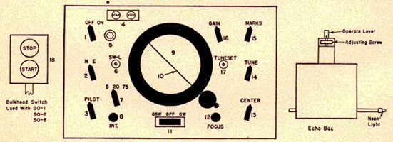
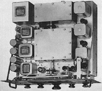
72. SO Search Radar
Accessory Control and Indicator Unit
(Catalogue of Naval Electronic Equipment - April 1946)
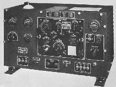
RADIO GEAR
Since first serving as the Army mine planter the General Samuel
M. Mills and until being scrapped as the Pequot in 1947, the ship's radio room
went through numerous generations of equipment upgrades. As technology
improved and the ship's mission changed, existing transmitters, receivers,
walking talkies, and direction finding gear were routinely upgraded to the
latest technologies. Work requests and maintenance documents from Boston's
First Naval District Coast Guard Office obtained through National Archives
provide a snapshot of some of the changes and alterations made to Pequot's radio
equipment during WWII.
January 7th 1942
A T-15 Transmitter was removed and a TCE Transmitter was installed at an estimated cost of $2841.
 |
| 73. A TCE Radio Transmitter like this one was in service aboard the Pequot from January 1942 through March of 1944. (US Navy) |
July 7th 1942
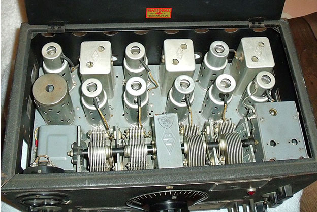
A RC-105 Receiver was installed to replace an HRO Junior Receiver. We believe the "RC-105" nomenclature was the Coast Guard designation for the newer model HRO "Senior" transmitter manufactured by The National Company, Inc.
 |
 |
 |
| 74. The HRO Junior Receiver and close-ups views of the radio's precision tuning dial | ||
 |
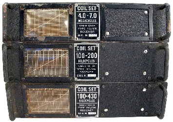 |
| 75. 1940 "HRO Senior" Model radio receiver and three rack mounted coil set units for the RC-105 required to pick up transmissions between 100 kilocyles and 7.0 megacycles. (Western Historic Radio Museum) | |
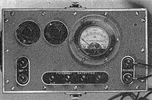
Ham radio enthusiast Brian Harrison has provided the Pequot project photos of a another WW-II era Coast Guard RC-105 receiver complete with R-115 speaker from his collection of vintage communications gear. See: http://qrz.com/db/kn4 Thanks Brian!
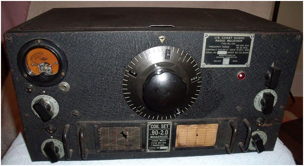 |
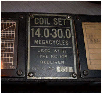
| In addition to the .90-2.0 Megacycle coil set installed in main radio chassis Brian's collection includes a separate coil set for transmissions in the 14 to 30 megacycle frequency range. |
 |
 |
 |
A look inside reveals the heavy duty construction of this sea going radio receiver with vacuum tubes and critical electronics covered and protected. |
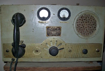
February 16th 1943
Per a December 1942 radio log correction we see that a TPC-119 Transmitter was installed on the Pequot. This was a portable emergency radio transmitter often installed in life boats. We speculate that rather than it being used as a life boat radio it may have been used for portable communication between Pequot and the crews out in the dory and launches who were marking loop cable installation points.
March 15th 1944
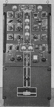
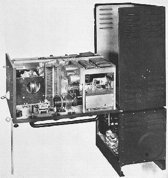
A TCE Transmitter along with T-6-A, and T-4 equipment was removed and a TDE and T-106 transmitter was installed. During this same period of maintenance an RBO Receiver and its associated alternator were installed "in the ward room aft."
 |
 |
|
76. TDE Transmitter control panel and a side view showing how the top electronics rack tilted forward 90 degrees onto a support post for electronic servicing and maintenance. (US Navy) |
|
 |
|
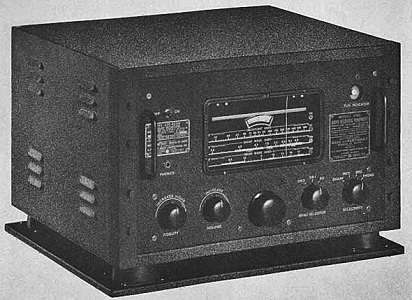
77. An RBO radio receiver like this one was installed in the Pequot's rear cabin "Ward Room," This was probably the radio Seaman Mike Luongo told us about that the crew used to listen to war news, Armed Forces Radio entertainment programs, and baseball games. (US Navy) |
 |
|
78.
This top view of the RBO receiver chassis shows the rugged industrial
strength construction of this vacuum tube radio. The robust specifications
of this reciever far exceeded home radios of the time. This unit was
intended to handle constant vibrations, physical shock, and the rigors of
service aboard a military ship at sea. (US Navy) |
January 19th and 29th 1944
Within the 1st Naval District Coast Guard Office in Boston a series of memorandums from the Assistant Chief Operations Officer detail how the Pequot was provided with portable radios including four SCR-536 "Handy Talky" units specifically for operational testing purposes and to provide a comparative test between the SCR-536 and a Model TRP-114 radio. Four TRP-114 systems were assigned to the Pequot and two were loaned to the Army for experimental use.
"The purpose of this test is to determine the suitability of the SCR-536 equipment for providing communications with ships' boats and to determine the relative merits between this equipment and the model TRP-114 equipment which is now undergoing tests on this vessel."
 |
| 79. The Coast Guard used communications between the Pequot and crews out in the launch during loop cable work to test the serviceability of different portable radio systems. (Seaman Mike Luongo) |
 |
 |
|
80. An SCR-536 Radio Set with an 18" ruler to provide visual scale, and an illustration showing the features of this "Handy Talky" which operated at 3.5 to 6.0 megacycles with 0.27 watts of power. It was designed for short range two-way voice communications. A 44 inch whip antenna telescoped into the handset for storage. When the antenna was pulled out the radio automatically turned itself on. With a range of 100 feet to 1.5 miles this radio was designed so that anyone could easily use it during combat conditions by simply pulling out the antenna and pressing the large button on the side to transmit. (US Navy & US Army) |
|
 |
 |
|
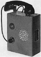
81. The TCO-2 and TCO Remote Control Unit were specifically designed for ship-to-ship and ship-to-shore communications. (US Navy) |
|
 |
 |
|
82. A vintage TCO-2 radio from a private collection (Nick K4NYW/virhistory.com) |
|
CABLE DETECTION EQUIPMENT
In addition to laying down indicator loop, communication and power cables the Pequot spent a great deal of time pulling up damaged cable and repairing it. Often anchors from cargo ships who were off the East coast preparing for convoy runs to England and Russia would snag undersea cables and damage them or break them completely. By towing a grappling hook on the end of a rope and dragging it along the seafloor the Pequot would retrieve dysfunctional and broken cable, haul it to the surface, then repair damage or splice the ends of broken cable back together. A very tedious and time consuming operation when sitting stationary. Quartermaster Lou Carhart tells us that Captain Lars Sande had the uncanny ability to snag underwater cables, "The old man was pretty good at that. Every time he came up with a cable on".
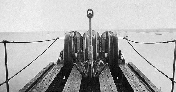 |
|
An undersea cable grappling hook at the stern sheaves on the Great Eastern cable ship 1865. (National Maritime Museum) |
To help things out and to pilot test some 1940s state-of-the
art technology the US Navy Bureau of Ships (BUSHIPS) provided the Pequot
"Submarine Cable Locating Equipment" which they had "recently developed, and
now have under manufacture." Among the Pequot records we've obtained from
national archives is an October 1st 1943 communication to Captain Sande from
the Coast Guard District Office in Boston informing him that the Bureau of
Ships would be delivering a cable locator directly to the Pequot. "This
equipment is a modification of a similar device made up experimentally a few
years ago in the Coast Guard Cable Laboratory. It consists of an interrupted
tone source which is connected to one or more conductors in the cable, and a
pickup device with associated amplifier, which is towed across the cable
area. Its purpose is to locate and identify an individual cable and reduce
the time required for dragging."
We believe that this unit may have been a Model OBB Cable.
 |
 |
|
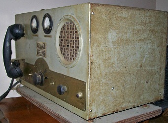
Model OBB
Cable Detecting Audio Amplifier and Audio Oscillator (Catalogue of Naval Electronic Equipment 1946) |
|
BUSHIPS offered a number of these devices to the Coast Guard for use on cable repair vessels which frequently laid and repaired underwater cables. In addition to delivering one of these units to the Pequot at Constitution Wharf in Boston, one was provided to the 12th Naval District Depot Coast Guard Telephone Repair Shop at Yerba Buena Island, in San Francisco, California and to the 13th Naval District Coast Guard Telephone Repair Shop at Yerba Buena Island, in San Francisco, California and to the 13th Naval District Coast Guard Telephone System Office, in Port Angeles, Washington.
"Shipment will be accompanied by an instruction book covering its operation. It is suggested that it be tried out whenever the necessity arises for locating a Navy or Coast Guard cable in connection with repair work. A report is requested of the results obtained in the operation of the equipment, its desirability for general issue, and any recommendations for its desirability for general issue, and any recommendations for its modification that may appear desirable."
Detailed Specifications on the OBB Cable Detection Equipment
can be found in the 1946 Catalogue of Naval Electronic Equipment:
http://archive.hnsa.org/doc/ecat/index.htm
Every effort has been made to trace and acknowledge copyright. The authors would welcome any information from people who believe their photos have been used without due credit. Some photos have been retouched to remove imperfections but otherwise they are true to the original.
FEEDBACK
If you have comments or queries specifically
about the Pequot or her Escort Ships, please contact
Chip Calamaio
chipaz@cox.net, Phoenix, Arizona, USA. (H) 602-279-450.
Click here to go to the Pequot Main Page
Research and design: Chip Calamaio and Richard Walding