HOW THE ANTI-SUBMARINE HARBOUR DEFENCE SYSTEM WORKED
Indicator Loops
are long lengths of cable laid on the seafloor of harbours to detect enemy
submarines. They were developed by the Royal Navy in the early 1900s and first trialled at the end of WW1.
They were then successfully deployed in WW2 in
British ports both at home, in the Dominions (Australia, Canada, New Zealand,
South Africa, Kenya, Ceylon, Penang) or in allied harbours (Iceland, Holland,
Dardanelles). By 1942 the United States had adapted this technology for its own needs. This page is about how they worked. |
If you have any feedback please email me: Dr Richard Walding Research Fellow - School of Science Griffith University Brisbane, Australia Email: waldingr49@gmail.com |
LINKS TO MY RELATED PAGES:
Indicator Loops - an overview (YouTube, 70 minutes)
- Indicator Loops around the World (Home Page)
I'd like to thank my grandson Daniel Walding for his encouragement in making these webgaes.

ANTI-SUBMARINE DETECTION SYSTEMS
Numerous methods of locating submarines have been developed over the years. As well as time-honoured visual sightings, they include: radar (surface), ASDIC or sonar (underwater, electromagnetic radiation emissions, heat sensing, exhaust analysis, sea lions, pelicans and importantly, in the context of this article, magnetic sensing.
One method relying on magnetic properties is the anti-submarine indicator loop.
It relies on the production of an induced current in a stationery loop of wire
when a magnet (in this case, a submarine) moves overhead. Even if wiped or
degaussed, submarines still have sufficient magnetism to produce a small current
in a loop. The technology was developed at both the Admiralty Experimental Station at Hawkcraig (Scotland)
from 1915 and later at the AES Parkeston Quay, Harwich, England. It was sent to various Commonwealth countries for deployment. For example, all of the loop materials used in Australia were of British origin ("Admiralty Pattern") although Australian-made equipment became available from about 1942 onwards. There was a great spirit of cooperation during the war. The RAN operated as part of the RN and there was a continuous exchange of officers as well as unhindered access to RN and USN technology. In the USA, the indicator loops were known as 'loop receiving stations'.
If an indicator loop indicated the presence of a vessel, the two
possibilities were "sub" or "non-sub". If no surface ship were sighted usually a
ship would be sent to drop depth charges. It had to be an enemy submarine
because friendly submarines always entered port surfaced. In several cases, the
loops were positioned beside controlled minefields in which the mines were connected by electrical cable back to a mine control hut on shore and the mines could be detonated manually
by an operator there.
The first recorded use of indicator loops was at Dumpton Gap, Broadstairs -
near Margate, on the coast east of London. These operated from 27 April 1918
until the armistice on 11 November that same year. They were also used at Scapa Flow, in the Orkney Islands at the northern tip of Scotland. Here the Royal Navy stationed its Grand Fleet and
the various entrances were protected by observation contact minefields. A ship
would need to bump into one of these mines and that would close a switch and
send a signal back to the shore station that contact had been made. The
operator in the shore station would examine the minefield with his telescope and
check the log to see if any friendly ships were expected. If there was no ship
over the minefield it was assumed that an enemy submarine had made contact with
the mine. The switch would be closed and a large current sent out by separate
cable to detonate the mines. From the moment of contact to the explosion would
have to be a matter of seconds.
With the successful operation of the Dumpton Gap Indicator Loop defences, the
Admiralty decided to convert the observation contact minefield at Scapa Flow to
"loop" minefields. A loop of cable was placed in a rough rectangle several
hundreds of yards long by perhaps 60 yards wide around the line of mines. When a
ship passed over the loop a shore-based galvanometer would indicate its presence
by the movement to the left or right of a centred needle. When the needle
crossed the centre position on its way back from its maximum deviation the ship
would be over the centre of the loop (and hence over the mines). The mines would
then be fired electrically by the shore-based observer in the mine control hut.
The one and only time in World War 1 that this happened was on 28th October 1918,
when German U-Boat UB-116 was destroyed in the controlled minefield at Hoxa Sound with the loss of 34 crew. In his book From The Dreadnought to Scapa Flow, historian Arthur Marder wrote: UB-116 was blown up in one of the loop minefields which were the inner defence. These were lines of mines, each surrounded by an electrical indicating loop. When the observer noticed the tell-tale needle of a loop deflected and saw that there was no surface ship there, he pressed the button and the line of mines went up.
Several books claim that minefields at Scape Flow were converted to loop
minefields in 1915. This is quite incorrect and a misunderstanding of the
meaning of "controlled" and "electrically detonated". These words apply to loop
minefields (which are "controlled" and "electrically detonated") but they apply
equally to the controlled "observation" minefields used from 1915 until 1918.
The difference is that the loop minefield had a "loop" (either a indicator loop,
a guard loop or a mine loop). In 1919 indicator loops as well as loop controlled
minefields were installed at Scapa Flow - but that is another story.
Other places where indicator loops were installed include:
England: Straits of Dover, Portsmouth, Portland, Plymouth, Falmouth,
Scotland: Firth of Forth (May Island), Loch Long, Oban Bay, Rosyth and Cumbrae
Ireland: Berehaven (planned), Queenstown (planned), St George's Channel, North Channel
Other Royal Navy ports: Hong Kong, Singapore, Penang, Alexandria, Malta, Haifa (Israel), Alexandria. Australia: Sydney, Darwin, Fremantle, Broken Bay, Newcastle, Moreton Bay, Brisbane River, Port Moresby
New Zealand: Auckland, Christchurch, Wellington
Canada: Saint John, Digby and Prince Rupert
United States: The USN set up 'loop receiving stations' mostly on the East Coast. They include:
- 1B Bailey Island, Casco Bay (Maine)
- 1B South Portland at Cape Elizabeth (Maine)
- 1C North Scituate (Massachusetts)
- 1D Nahant, East Point (Massachusetts)
- 1E Gloucester (Massachusetts)
- 1F Peaks Island/Fort Williams (Maine)
- 1G Portsmouth (NH)
- 1I South Westport (Massachusetts)
- 1X Argentia (Newfoundland)
- 1X Woody Island (Alaska).
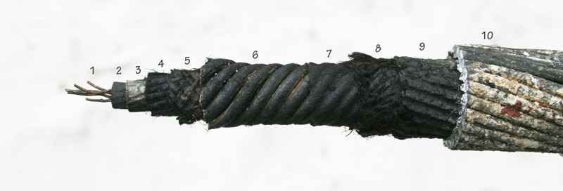
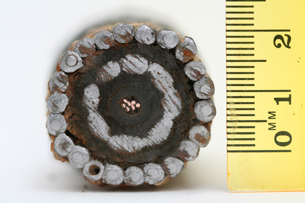
THE CABLEThis is the cable that actually detected the crossings.
SINGLE CORE LEAD LOADED CABLE - ADMIRALTY PATTERN 1989 (W. T. Henley Telegraph Works Co.).
The "1989" cable was made principally by W.T. Henley's Telegraph Works Company at Gravesend, downstream on the south bank of the Thames. The other manufacturer was Siemens, London. The "1989" cable consists of a single core of seven strands of 0.029" tinned copper wire (#1) covered with three layers of India rubber (#2 in Fig.) on which is attached the manufacturer’s identification tape. Covering this is a layer of thin (0.5 mm) waterproof tape (#3) and wound with 16 strands of jute yarn each about 2 mm in diameter (#4). The jute yarn layer is then covered with a tarred hessian mesh (#5) and a spirally wound anticlockwise layer of eight strands of 3.2 mm diameter pure lead wire (#6). These lead windings are covered with more waterproof tape (#7), 24 strands of a tarred jute serving (#8), and one more layer of hessian tape (#9). The whole is protected with a clockwise winding of 22 steel armour wires (#10), each about 1.9 mm diameter covered in pure lead 0.8 mm thick (Fig. ). Then there is a braiding of dressed hemp yarn wrapped over hot pitch and resin (not shown), and finally a preservative coating. The final diameter is 1.35" (34.3 mm). It has a linear density in British imperial units of 6.09 tons per 2000 yard mile in air (6.8 lb per yard) or in metric units: 3.4 tonnes/km (3.4 kg/m). It weighed 6.09 tons per 2000 yard mile in air (6.8 lb per yard) and 4.56 tons per mile in sea water. Its breaking strain was 3.00 tons and had a resistance of 11 Ω per mile. The cost in 1938 was ₤180 per 1000 yards (which equates to approximately ₤9000 per 1000 yards in today’s money). In some harbours the Royal Navy used ADM Pattern 13142, a 7-core lead-loaded cable. The electrical resistance was 6 ohms/km. Henley's also made another type of cable offered as a replacement for the Type 1989. It was Type 6190A - a lead covered single core of 28 strands or 0.012" tinned HD (hard drawn) cadmium copper wire. The cadmium increased the breaking strain from 250 lb to 470 lb.
TAIL CABLE
The ADM Patt. 9610 was a 4 core, 7 strand, 0.029" cable used for loop tails. It was made by Johnson & Philips (UK) in 1941. It has a diameter of 25 mm. The longitudinal section shows the four central cores insulated with 5mm diameter rubber (3 are white, one black), surrounded by 18 mm diameter rubber bedding. Also visible is the 25 mm wide cotton gauze around the rubber; the central square white rubber core (not visible) and the 22 strand steel armour. This cable was supplied by Johnson & Philips. You can just make out the reversed name transferred on to the white rubber.
HOW THE LOOP WORKS
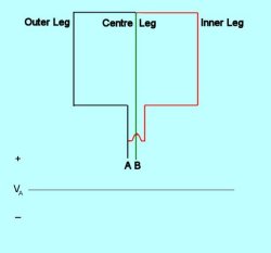
The most common loop arrangement was the 'three-legged loop' as shown in the figure below.
The loop cable was typically 5000 yards long and 200 plus 200 yards wide. The centre leg joined the top cable in a waterproof junction box. In the lower junction box, the centre leg and the two outer legs were joined to the 'tail' to shore. The tail was usually four core, seven strand, the spare core being used for doubling-up the copper wires to reduce resistance. The right outer leg conductor was connected to a "Box, Balancing" (in Navy parlance) which was just a variable resistor used to equalize the resistance of both half-loops. This was located inside the Loop Control Hut on shore.
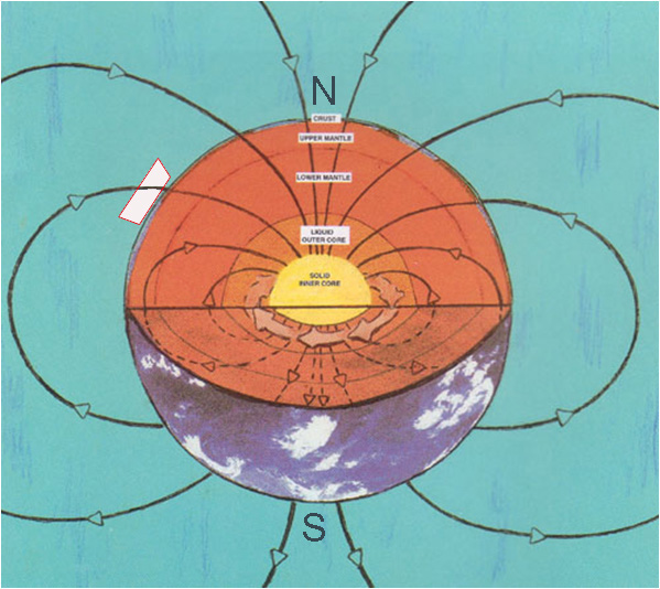
MAGNETIC FIELD OF A SUBMARINE
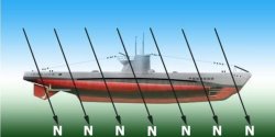
The two figures below show the Earth's magnetic field (left) and how the magnetic field "threads" through a ship being constructed in the Northern Hemisphere (at say Latitude 50 degrees - perhaps in England, Germany or Japan).
Earth's magnetic field Ship in Earth's field (northern hemisphere)
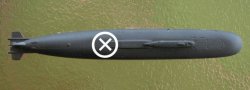
The magnetic field threading a submarine being built in the Northern hemisphere may be represented from the side using an arrow (figure, left) or from above using a cross (photo, right):
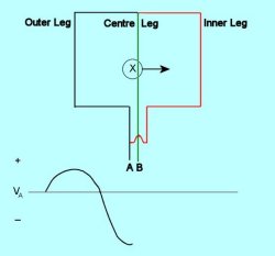
A submarine built in the Northern Hemisphere becomes "North-down" Looking from above, the magnetic field of a North-down sub is represented by a cross (X) showing that the field is pointing away from the viewer. When a magnetised vessel passes over a conductor, an induced voltage is produced. This is recorded on a paper chart. The diagrams below show the successive stages of a submarine crossing a 3-legged loop from left to right - as depicted from above the submarine.
The first figure shows the three-legged loop before a submarine approaches. No voltage is registered on the galvanometer.
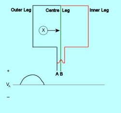
As the submarine crosses the outer leg, a voltage is induced (terminal "A" becomes positive with respect to "B" (which is earthed).
As the submarine is in the centre of the outer loop, no voltage is induced as the sub's magnetic field is not cutting any leg of the loops (terminal "A" returns to zero with respect to "B" (which is earthed).
As the submarine crosses the centre leg, a voltage is induced (terminal "A" becomes negative with respect to "B" (which is earthed). However, as the centre leg is common to both loops, double the voltage is produced. It may be easier to think of the centre leg as made up of two wires, one from each loop. As the submarine passes the centre of the inner loop, no voltage is induced as the sub's magnetic field is not cutting any leg of the loops (terminal "A" returns to zero with respect to "B". As the submarine crosses the inner leg, a voltage is induced (terminal "A" becomes positive with respect to "B". And as the sub continues to move away to the right from the loops the voltage returns to zero.
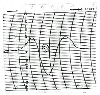
The final waveform looks like this. It is called an inverted "William" Pattern.
Sample chart from Casco Bay (USA) loop station in 1943 The interpretation of a loop signature and some more examples from the United States can be found at my webpage: Reading Loop Signatures.
THE LOOP HUT
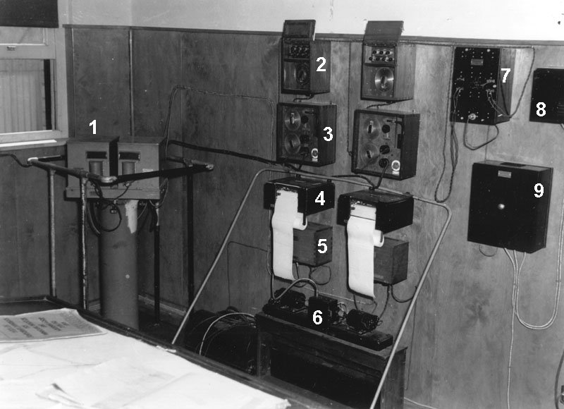
The tails from the loop cables entered the hut and were connected to the Box Balancing (No. 2 on the photo below). This was connected to the Box Adjusting (No. 3) followed by the Integrator (inside No. 1). Light from the Integrator shone on to Photo Electric Cells (inside No. 1) whose signal was fed into the Amplifier (no. 5) and on to the Recorder (No. 4). The Recorder was driven by a motor (No. 6). Morse code signals picked up by the loop cables were amplified by the Loop Indicating Signal Apparatus (LISA) (No. 9) and were fed into the LISA Loudspeaker (No. 8) to be heard. Power for the equipment came from the Input Transformer Box (7).
The Box, Balancing
The Box, Adjusting
The Box, Balancing, Pattern No. 2327.
The box, balancing, is a teak box fitted with a panel on which is mounted a double scale concentric potentiometer and an ebonite block carrying a series of terminals and a double pole change‑over switch. To eliminate thermo-e.m.f.s, the terminals and change‑over switch and the resistance coils of the potentiometer are all constructed of copper.The potentiometer resistance has a total value of 294 ohms, made up of 28 steps of 10 ohms and 28 steps of ‑1 ohm. The three upper terminals on the ebonite block are marked "Inner," "Middle","Outer," for connection to the corresponding legs of the loop. The change‑over switch allows the balancing resistance to be inserted in either half of the loop, or the loop to be isolated for testing purposes. A two‑way cable socket marked "A" is fitted in the bottom of the box, which is connected to the adjusting box by a two‑way cable connector labelled "A" which plugs into this socket. The box is secured by three lugs to porcelain insulators mounted on the battens. These lugs lie flat in recesses in the box for transport.
The Box, Adjusting, Pattern No. 2324.
The box, galvanometer adjusting, is a teak box fitted with a panel on which are mounted the following components:
(a) An arrangement of double scale potentiometer and resistances connected to an inert cell, and a change‑over switch for the purpose of injecting known e.m.f.s into the loop circuit. This is known as the e.m.f. injector.
(b) A single scale potentiometer for shunting the loop. This is known as the shunt.
(c) An arrangement consisting of a fixed coil and a movable magnet for the purpose of linking known numbers of lines of force with the loop circuit. This is known as the coil injector.To eliminate thermo-e.m.f.s all parts which enter into the loop circuit are made ‑of copper or gold‑silver alloy. Connections to the balancing box and the integrator are made by means of two‑way cable connectors labelled "A" and "F" which plug into sockets marked "A" and "B" respectively.
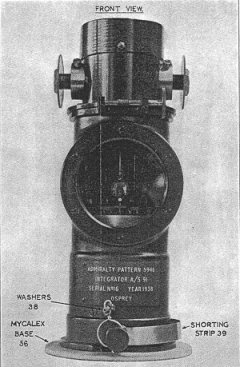
The Integrator A/S 91.
The integrator is in reality a fluxmeter, which may be defined as a moving coil galvanometer specially designed for the measurement of magnetic fields, its deflections being determined solely by the total quantity of electricity discharged through the moving coil and being practically independent of the rate at which the discharge takes place. The special design of the integrator is such that its accuracy for measuring changes in flux linkage in the loop is very high, even when the change takes place very slowly, such as when a vessel crosses at only one or two knots. This means that the size of the signature obtained from a crossing vessel will be approximately the same no matter at what speed the vessel is travelling, since the integrator measures the actual field emanating from the vessel and this does not depend on its speed.
The Integrator as depicted in the "Indicator Loop" Confidential Book I bought this Integrator for $250 from a collector in New York. It came from a deceased estate in Canada. I understand that it was used at one of the Canadian Loop Control Stations in WW2.
The constants of the integrator are as follows:
Periodic time: Approximately 80 seconds.
Flux sensitivity: 600 lines of force per I millimeter deflection at 100 centimetres scale distance.
Direct current sensitivity: 12,000 millimetres per microampere at 100 centimetres scale distance.
The main constructional details of the integrator are shown in Figure 12. A coil of fine copper wire (1) has two mirrors (2) and (3) attached to its upper edge, The upper or main mirror is convex and is used for reflecting a beam of light on to two photo‑electric cells. The lower, or auxiliary mirror, is plain and is tilted slightly upwards ; it reflects light from the same source on to a small scale. The whole is suspended by a robust phosphor bronze strip (4) so that the coil lies between the curved pole faces of a strong permanent magnet (5) and is free to rotate in the small air gap between the pole faces and a cylindrical core (6). The upper end of the suspension strip is soldered to a brass arm (7) mounted on a disc (8) secured to the upper face of an adjusting sleeve (9) clamped in a fixed collar (10). Rotation of the disc permits regulation of the torsion of the suspension strip. The complete upper anchorage assembly is known as the torsion head and is protected by a soft iron cover (11). Current is led into and out of the moving coil by two fine copper spirals (12) connected to two terminals (13) at the base of the instrument, the back terminal being earthed to the casing (14) and marked " +ve " Attached to the upper end of the main mirror is a glass tube (15) across the top of which is mounted a very small magnetised needle (16).
The needle lies in the uniform field produced by two auxiliary magnets (17) the strength of this field can be adjusted by altering the distance between the magnets by means of the knurled discs (18). The auxiliary magnets are mounted in a soft iron shell (19) closed at the top by the soft iron cover and at the bottom by two semi‑circular soft iron discs (20) bored to give clearance to the adjusting sleeve. The magnets are locked in their correct setting by the set screws (21), and this setting should on no account be disturbed. The shell ‑and its associated magnets, cover, etc. (the whole known as the magnetic head) is rotatable relative to the lower half of the integrator by means of the knurled disc (22) operating the worm (23) and thread (24) ; it is held in place by three collared keep screws (25), which do not, however, prevent its rotation. Rotation of the magnetic head alters the zero of the integrator and is used for zero adjustment should this be necessary on first setting up the integrator on its table.
A clamp is fitted to provide a means of securing the coil system for transport purposes to eliminate danger of breakage. The clamp consists of a cork pad (26) free to slide clear of the projecting boss of the lower copper coil clip (27) ; the pad is mounted on a movable springy phosphor bronze arm (28), whose other end bears upon an eccentric (29). Rotation of the eccentric by a lever (30) raises the arm and forces the pad to travel upwards until it lifts the coil and just holds it against the core piece of the main magnet. In this position the projecting boss of the upper coil clip (31) just fits into a coned cork pad (32) carried on a fixed brass arm (33), thus preventing vibration of the mirror, glass tube, etc., mounted on the upper edge of the coil. Damage due to possible vibration of the upper end of the glass tube is prevented by a cork ring (34), secured inside the adjusting sleeve, and through which the tube passes with a little clearance. The eccentric is so designed that when locking the coil it has to rotate past its dead centre, which prevents it from unlocking of its own accord during transport. A plain glass window (35) is let into the front of the instrument.
Admiralty Experimental Station at Hawkcraig
A fascinating book - "Listen Up!" - has been produced about the Hawkcraig AES and HMS Tarlair by the Aberdour Cultural Association, 2014 [ISBN 978-0-9929470-0-2]. The book was written by Diana Maxwell and is available for purchase from the Association for about £6. Contact them at: aberdour.culture@outlook.com. My thanks to Lewis Banks for a copy of the book.


The book has a Forward by local historian Mr Edward Dunstan:
This volume by Diana Maxwell describes in detail the Hawkcraig Admiralty Experimental Establishment Station in Aberdour, Fife, during the First World War. It is a valuable addition to our knowledge about this little known, but important, research station.
The German Unterseeboot ("undersea boat") was an incredibly powerful weapon during the First World War. In the four months between October 1916 and January 1917 1.4 million tonnes of Allied shipping was sunk by these vessels, most notoriously on May 1915 the Germans breached international law and sank the ocean liner RSS Lusitania, a non-military ship, causing the deaths of 1198 passengers and crew.
The work done at the Hawkcraig Point Station to develop a tool to assist in the defeat of the German U-boat menace was an incredibly important part of the Allied war effort.
The author, a retired Superintendent Radiographer, deserves high praise. Her dedication to this project is evident on every page. She has spent many hours researching local records and visited every inch of land over which the centre was located. The personal accounts of those who remember the Station and the photographs bring the whole story to life. This is altogether a well researched, moving and readable volume telling the story of a relatively minor Research Station, which had effects far beyond those that might at first have been imagined.
This book should be seen as a tribute to the Civil and Military Scientists together with their Researchers who contributed to some major technological advances in detection of the German U-boot.
Mr ERR Dunstan MBBS, BSc, FRCS, T&O
Clinical Lead Orthopaedics, NHS Fife
Appraisal Tutor NES Scotland
Author of "The Forgotten Battle of Herouville"
Special Interest, The development of Trauma Surgery in WW I
Edinburgh 2014
RETURN TO LOOPs OF THE WORLD HOME PAGE:
Indicator Loops around the World (Home Page)