and Harbour Defence Asdics (HDAs)
 |
If you have any feedback please email me: Dr Richard Walding Research Fellow - School of Science Griffith University Brisbane, Australia Email: waldingr49@yahoo.com.au |
WHAT IS IT?
|
|
Photo right: Type 135 HDA and tripod being lifted from the waters of Trincomalee Harbour, Ceylon, by the cable-layer HMS Bullfrog in 1945. This photo was supplied by Captain Walter J S Flett (RN), Findochty, Scotland who was an Ordinary Seaman aboard Bullfrog from late 1945 to early 1946. This is the only photo of the British HDA dome known. The total height of the HDA was about 12 foot with the dome being about 1'8" diameter and 3' long. |
 |
The USN Herald unit operates on the same principal:
 |
| Herald being lowered in NY Harbor. Photo supplied by Jim Carpenter, son of Lt Carpenter, Commanding Officer at Fishers Island, New York. The Herald was in the form of a triangular-based pyramid with a height of about 10-12 foot. |
 |
 |
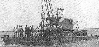
| US Navy pontoon barges are usually used at advanced bases in transporting supplies from ship to shore. They are also very helpful when supplied with a crane, in planting Herald sea units (1944). | Herald shore terminal unit being tuned by student watchstanders at the National Training School, Fishers Island, NY - 1944. |
DEVELOPMENT
Asdic was a term used
to describe echo location and ranging using high frequency sound waves. It grew
out of experiments undertaken by French scientists in the early 1900s on the
propagation of sound in water. Of particular note is the Fessenden
electromagnetic oscillator which was a precursor to the modern transducers used
in sonar, the term now applied to Asdic operations. Other French scientists
contributing greatly to the work were Langevin and Chilowsky who developed
techniques for transmitting and detecting the sound waves. In 1915, NZ
scientist Ernest Rutherford and scientists from the British Bureau of
Investigation and Research (BIR) developed the process further and the first
Asdics were ordered by the Royal Navy in June 1918. In the USA, experiments
continued at Columbia University which lead to the formation of research teams
combining the US Navy, the Submarine Signal Company, General Electric and
Western Electric at Nahant, MA. Asdic research stepped up
at the start of WW1 but it was not ready by the end of the
war, and didn't get to sea until 1920, when one was evaluated on the cruiser HMS
ANTRIM. Four patrol vessels were also fitted with Asdic on an experimental
basis, leading to adoption of a production Asdic system in July 1922. British
submarines were fitted with Asdic beginning in 1926. It was in service in
British destroyers from 1928.
The HDA was developed in the late 1920s at HMS Osprey (Portland Naval Base, England). It was given low priority and the first model was not ready until March 1932 when placed 1000 yards off the Portland breakwater. An improved HDA was laid 3 miles off the same breakwater in 1934 in conjunction with indicator loops. The valve transmitter of the early set was replaced with an high frequency motor alternator (HFMA) and a resonant circuit. After this, the first model with a number (131) was introduced.
By December 1941, the Admiralty was worried about midget submarines entering ports (against which the standard indicator loop was ineffective), particularly after Italian human torpedoes made daring attacks on the harbours at Alexandria and Gibralta. The Type 131 HDA was not effective against small targets so an improved HDA (Type 135) was designed at the Underwater Experimental Establishment at Fairlie by the naval scientist H F Willis.
Whereas the Royal Navy used quartz oscillators,
the US Navy based their oscillator on magnetostriction. Both the Admiralty and
the National Research Laboratory (USA) worked on magnetostriction, their paths
diverged before the war and each chose alternative methods.
HDA SCHEMATIC
Operation of the HDA can be seen in the following schematic (Figure 1):

MODE OF OPERATION
Power was generated by a Mark 2VSO Ruston Vertical Oil (Diesel) engine producing
15 - 16½ HP at 1000 RPM, connected by belt drives to a 220V,
7kW DC Generator for the HDA and a 110V 2kW DC Generator for the Indicator
Loops. This was housed in a 18' x 10' concrete generator hut about 100 m from
the control hut.
 |
 |
| The Generator Hut at RAN 4, Bribie Island. | Artificer's Workshop at RAN |
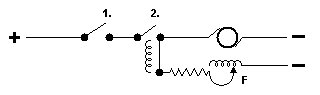
Board Charge-Discharge
High Frequency Motor Alternator
 |
|
|
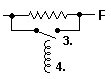
Figure 2 - To start, close SW 1. Solenoid closes SW2. Motor starts with resistor in. |
Figure 2 - At run, resistor is shorted out by SW3 which closes when back EMF from motor weakens holding off coil 4. |
At the opposite end of the HFMA to the commutator was a simple governor (Figure 4):

Figure 4
The Disc and Ring are in the field circuit. If the motor speeds
up, centrifugal force straightens the spring, breaking contact between disc and
ring, opening the field circuit, slowing the motor. In operation, this is
continuous, sparking is always visible, and the carbon ring must be frequently
checked and replaced.
 |

|
| The HDA Room at RAN 4 | Some 2-core cable in the HDA Room |
Transmitting Panel
Constantly charged by the HFMA, this resonant circuit was discharged to the oscillator by the automated send/receive key (S/R Key) on the Transmitting Panel. The key itself was a simple rotating arm motor type with limited movement thus:
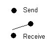
Figure 5
Perfect cleanliness was the answer here plus a smear of Pure Medicinal Vaseline. This substance was known in the service as "Starters" and the sight of it in a more senior officer's hand would terrify any midshipman.
The Amplifier
Four standard thermionic triodes were powered by the
batteries and operated thus (Figure 6):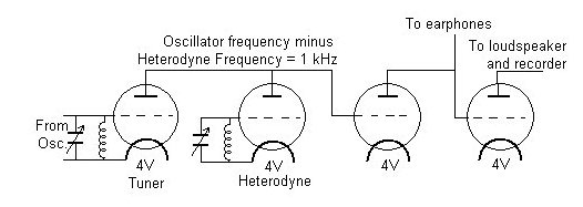
Figure 6
The output from the amplifier (tuner) was heterodyned by mixing the signal from the amplifier (e.g. 13 kHz) with a carrier signal generated by another oscillator within the amplifier that was 1 kHz higher or lower (e.g. 12 kHz). The resultant signal was the difference between the two (1kHz) which is audible and can be heard by the Asdic rating through headphones or a loudspeaker (a nice tone - just below the C above high C).
To adjust the frequency of the signal several changes had to be made to the equipment. For example, to choose a resonant frequency of 11 kHz (identification code "U"), the operator adds a set of copper discs stamped with the letter "U" to the governor of the HFMA which regulates its speed to produce an 11 kHz signal. He would also set the number of condensers on the transmitting Panel to "U", the Amplifier valve to "U" and the heterodyne also to "U".
|
|
|
|
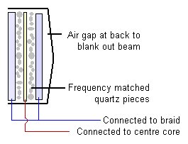
Figure 7: Diagram of the quartz oscillator. It has a diameter of about 15". |
A cut-away of a dome that would be lowered when a ship is using Asdic gear. The oscillator housing is in the centre. |
The Quartz Oscillator consisted of three steel plates
as shown in the figure above. Sandwiched between them were pieces of quartz of matched frequency. This circuit was connected via an armoured 2-core cable to a quartz oscillator housed in a pressure-tight bronze cylindrical dome about 2' long slung vertically (gimballed) under a 12' high tripod on the sea bed. An armoured 7-core cable delivered 220V DC to the Bearing Control in the Controlled Training Unit in the HDA Room and thence to the Training Motor in the dome out in the bay. This allowed control of the direction of the Asdic Beam in 5° steps (or 1° - 2½° continuous). The dome was filled with water and the dome itself had a window (originally Dermatine but later stainless steel) through which sound could pass without diminution in volume or change in frequency.Electrochemical Range Recorder
 First production model electrochemical range recorder A/S3, 1934. Instrument was slaved to the distance finder A/S5. Paper impregnated with potassium iodide starch solution contained in sealed tank shown in the right hand picture. Each roll of paper was 30 yards long and a black warning mark would appear on the right hand edge signifying the approach of the end of the roll. After its appearance, there was still sufficient paper remaining to complete the attack. Source: ADM 186/526, Osprey (HY), No. 25, Fig 34 A and B. |
HISTORICAL NOTE: precursor to the Asdic recorder
Stylograph
In the early days of the telegraph, a
variety of methods were used for recording the signal transmitted over the
wires. Bain's "chemical telegraph" used specially prepared paper: The battery
current, decomposed the salts in the paper and united with the iron point of the
pen-wire, left a light blue mark on white paper. Or, if the current were strong,
a dark blue mark would be left on the paper. The color of the mark depended upon
the quantity of the current upon the wire. During the magnetic storm of February
19, 1852, the current increased so much that a "flame of fire" followed the pen
and set fire to the paper. The following is an actual account from the journal
of an electric telegrapher:
Thursday, February 19, 1852
"Towards evening, a heavy blue line appeared upon the paper, which gradually
increased in size for the space of half a minute, when a flame of fire succeeded
to the blue line, of sufficient intensity to burn through a dozen thicknesses of
the moistened paper. The current then subsided as gradually as it had come on,
until it entirely ceased, and was then succeeded by a negative current (which
bleaches, instead of coloring, the paper). This gradually increased, in the same
manner as the positive current, until it also, in turn, produced its flame of
fire, and burned through many thicknesses of the prepared paper; it then
subsided, again to be followed by the positive current. This state of things
continued during the entire evening, and effectually prevented any business
being done over the wires."
Indicator Loops around the World (Home Page)